DX Coil Replacement for Harsh, High-Humidity Mushroom Farm Environments

Kennett Square, PA is widely known as the mushroom capital of the world. It is also located just a short drive from Capital Coil & Air’s sales office in West Chester, PA. Because of that proximity, we regularly receive requests from local mushroom farms to visit their facilities and measure failing DX coils for replacement.

Mushroom farms require precise climate control. Proper ventilation is critical because high CO₂ levels can negatively affect mushroom quality and growth. Humidity must also be carefully controlled. Mushrooms thrive in high-humidity environments, but too much moisture can lead to mold, bacteria, and serious crop losses.

That makes reliable HVAC equipment essential.

The Problem

One local mushroom farm had been dealing with multiple failing DX coils. Instead of replacing them, they had tried several temporary “band-aid” repairs. None of those repairs solved the issue.

As the coils continued to fail, the systems had to work harder to maintain the required growing conditions. That caused energy costs to rise while performance continued to decline.

A neighboring farm, which had already used Capital Coil & Air for several DX coil replacements, recommended that they call us to inspect the equipment.

What We Found

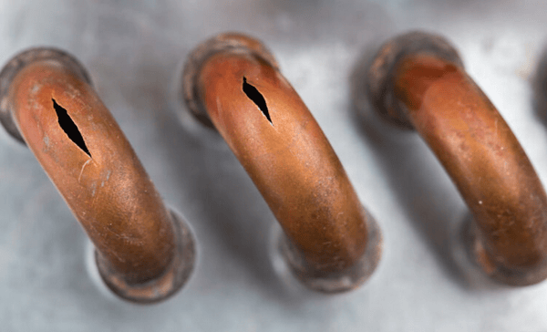
After inspecting several units, we found that the finned area on many of the coils had been severely damaged by corrosive elements in the air. The aluminum fins had deteriorated far faster than expected, which significantly reduced coil performance.

The original equipment had not included added coil protection, which made the coils vulnerable in such a harsh environment.

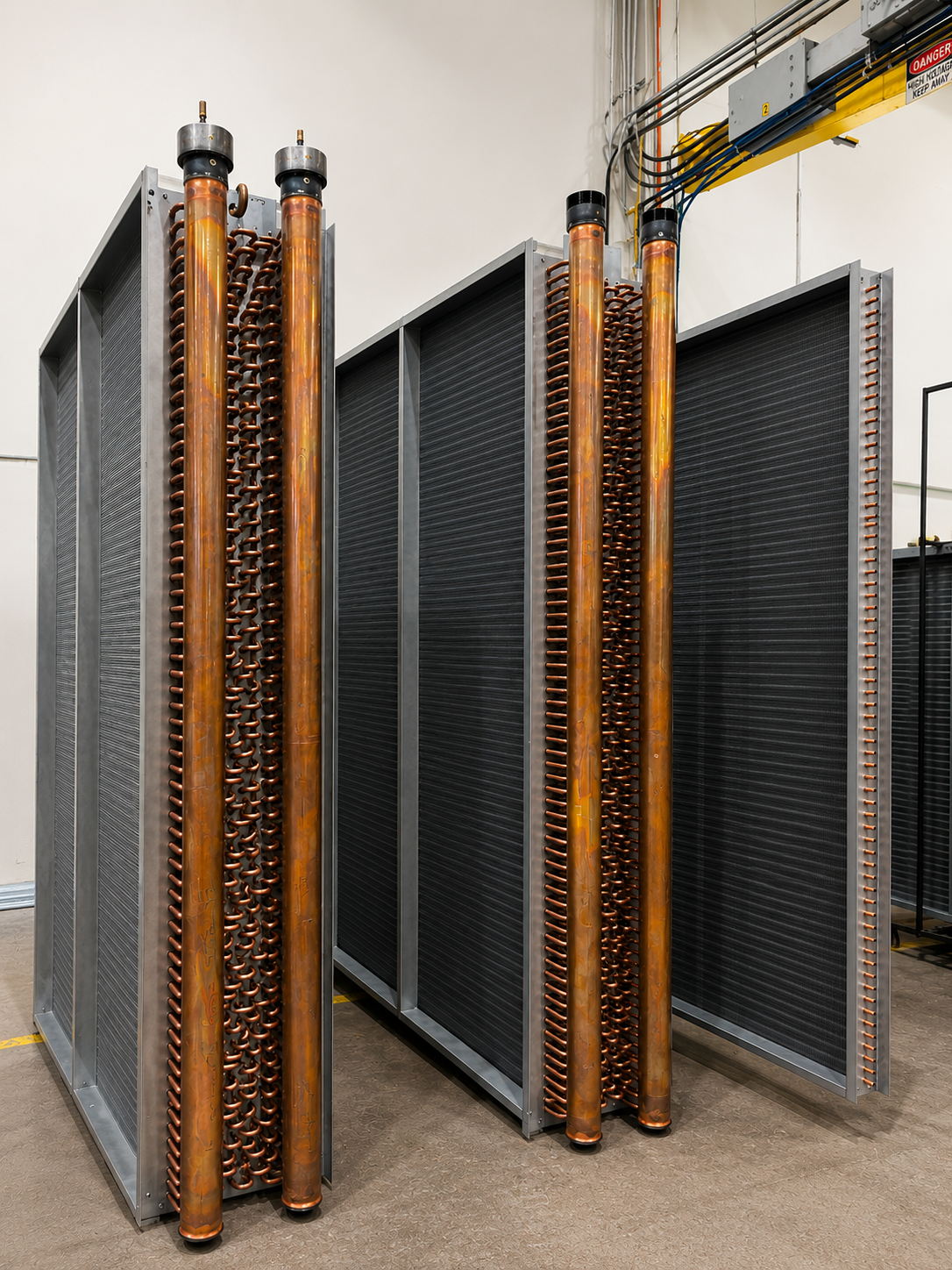
Because the new DX coils had to fit into the existing units, exact measurements were critical. We also recommended that any replacement coils include added protection, such as:

  • Epoxy coating
  • Stainless-steel casingDX Coil
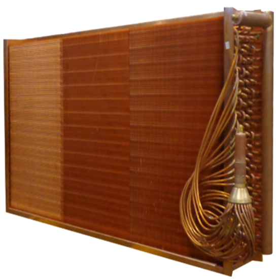
  • Copper fins
  • Other corrosion-resistant construction options

Without added protection, the farm would likely continue facing the same failures.

The Solution

The farm decided to start with one replacement DX coil as a test. Capital Coil & Air measured the original coil, built an exact replacement, and supplied the new DX coil with an epoxy coating for added corrosion protection.

The coil arrived a few weeks later and matched the original unit perfectly.

One year later, the replacement coil was still operating at full capacity with no visible damage to the finned area.

The Result

Because Capital Coil & Air was able to respond quickly, identify the true cause of failure, and recommend a longer-lasting replacement solution, the farm moved forward with ordering the remaining batch of DX coils.

That successful project also led to additional referrals throughout the local mushroom farming community. Today, Capital Coil & Air is a trusted HVAC coil replacement supplier for many of the largest mushroom farms in the United States.

When corrosive environments destroy OEM coils too quickly, Capital Coil & Air can build exact-fit replacement coils with the right materials, coatings, and construction options to extend coil life and protect critical HVAC systems.

RELATED POSTS

Now Offering R-454B Refrigerant for All DX Coils

What Does “Splitting” DX (Evaporator) Coils Mean

Cooling Coils & Moisture Carryover 


Coils and Counter-Flow: 5 Quick HVAC Questions Answered

In HVAC systems, understanding coils and counter-flow is critical for maintaining efficiency, preventing equipment failure, and ensuring long-term system reliability. Whether you work with chilled water coils, steam coils, DX coils, or hot water coils, correct installation and piping methods can dramatically impact performance.

Many HVAC issues begin with improper piping, poor condensate removal, and/or incorrect coil feeding. The good news? Most of these problems are completely avoidable when proper HVAC design principles are followed from the start.

This guide answers five of the most common questions about coils and counter-flow while explaining the real-world consequences of incorrect installation practices.

1. What Is Counter-Flow?

Counter-flow means air and water move in opposite directions through the coil.

  • Air: Rows 1 → 8
  • Water: Rows 8 → 1

This setup maximizes heat transfer and coil efficiency. Chilled water and DX coils are always designed for counter-flow operation.

Incorrect piping can reduce performance by 8–12%

2. Why Feed Water Coils from the Bottom?

Bottom feeding ensures all coil tubes receive even water flow.DX Cpil

Benefits:

  • Better heat transfer
  • Balanced performance
  • Prevents “short circuiting”

Top feeding can cause uneven flow and reduced efficiency.

3. What Is Water Hammer in a Steam Coil?

Water hammer occurs when steam hits trapped condensate inside the coil.

Results:

  • Loud banging noises
  • Pressure shock
  • Damaged coil joints and piping

Over time, this can lead to coil failure.

4. What Happens If Condensate Isn’t Removed?

Condensate can block steam flow and reduce heating performance.

Warning Signs:

  • One side of coil feels warm
  • Other side feels cool

Steam coils must:

  • Be pitched properly
  • Use steam traps and vacuum breakers
  • Drain condensate continuously

5. Do Steam and Hot Water Coils Need Counter-Flow?

No. Steam and hot water coils do not require counter-flow piping.Steam Coil

Key Rule:

The steam supply should enter high, while condensate exits low.

Condensate must always leave the coil properly.


Best Practices

  • Pipe chilled water coils in counter-flow
  • Feed water coils from the bottom
  • Properly drain condensate from steam coils
  • Install steam traps correctly
  • Follow manufacturer piping diagrams

If you have any questions or need assistance with installation, speak with one of our coil experts today!

RELATED POSTS

Tips on Hand Designation & Counter-flow

Chilled Water Coils & Moisture Carryover

Chilled Water Coil Circuiting Made Easy


Why Are HVAC Coils Made with Copper Tubes and Aluminum Fins?

HVAC Coils

It’s no coincidence that HVAC coils predominantly use copper tubes and aluminum fins. Copper is known to have exceptional heat transfer properties, while aluminum, although effective, does not match copper’s performance. When it comes to HVAC coils, the primary goal is either cooling or heating, which means heat transfer is a top priority. Right behind that? Cost. While copper is ideal for tubes due to its efficiency, using it for fins would be economically feasible only under specific circumstances. Consequently, the majority of HVAC coils are designed with copper tubes and aluminum fins, which provide an optimal balance of effective heat transfer and cost efficiency.

Fins play a crucial role in heat transfer, accounting for approximately 65% to 70% of the total heat exchange in any coil. The tubes contribute about 30% to 35%. To achieve optimal performance, it is essential to have a strong fin-tube bond. In HVAC terminology, fins are referred to as the “secondary surface,” while tubes are the “primary surface.” Interestingly, the secondary surface—aided by the expansive fin design—carries out twice the amount of heat transfer compared to the primary surface.

In the manufacturing process, the tubes are expanded into the fins, making the fins the secondary element. Given the fin density—typically at 8 to 10 fins per inch—here is significantly more surface area from the fins than from the tubes. This further highlights the importance of a robust fin-tube bond, as it is essential for the fins to perform effectively.

Understanding the materials used in HVAC coils is critical, and the reason copper and aluminum are the materials of choice for most coils is clear. Alternative tube materials such as aluminum, 304/316 stainless steel, and 90/10 cupro-nickel can be used, but none match the efficiency and cost effectiveness of the copper-aluminum combination.

At Capital Coil & Air, we are dedicated to assisting you with all your coil selection needs and look forward to collaborating on your next project.

RELATED POSTS

Why Is Fin Design On HVAC Coils Important?

Top 10 Tips to Measuring Coils

Did You Know? Facts about Commercial HVAC Coils


Replacing Carrier Chilled Water Coils

For HVAC professionals, replacing Carrier chilled water coils is a task that demands precision. One miscalculation in dimensions, connection types, or circuit configurations can turn a straightforward replacement into a significant challenge, leading to delays and complications like compromised airflow or customer callbacks.

Why Precision Is Critical

Carrier chilled water coils are engineered with extremely precise specifications. Even the slightest deviation can result in issues such as:

  • Airflow Restrictions: A poor fit can obstruct air movement, affecting system efficiency.
  • Inefficient Heat Transfer: Suboptimal coils may lead to inadequate cooling performance and increased energy costs.
  • Connection Misalignment: Mismatched connections complicate the installation process and can lead to leaks or failures.
  • Extended Installation Times: Inaccuracies often necessitate additional rework, wasting valuable time on the job site.

It’s crucial to explain the importance of attention to detail to your clients. A so-called “replacement” coil that doesn’t meet specifications can inadvertently introduce new problems rather than solving the existing ones.

The Capital Coil Advantage

In the world of HVAC, many coil manufacturers overlook the significance of these specifications, opting for oversimplified solutions that can create headaches later on.

Here’s where Capital Coil steps in. Whether you have:chilled water coil

  • A clear model tag
  • A partial number
  • Or even just a worn-out coil

We have the expertise to provide a reliable solution. Our team has extensive experience manufacturing the coil types you depend on daily, ensuring you receive high-quality products.

Cross-Referencing Capabilities

In many cases, we can cross-reference Carrier coil models accurately, thanks to our comprehensive manufacturing history. If direct cross-referencing isn’t feasible, we can also work from the drawings you provide, creating a custom solution that meets your precise requirements.

Take-aways 

Replacing a Carrier chilled water coil doesn’t have to be a gamble. By collaborating with Capital Coil, you gain a reliable partner who understands the critical elements of the job: ensuring a perfect fit, optimizing performance, and getting the installation right the first time. 

For additional information or to discuss your specific coil replacement needs, feel free to reach out to the Capital Coil team. Let us help you streamline your projects and enhance your HVAC services!

RELATED POSTS

Looking For A Trane Replacement Coil

Top 10 Chilled Water Coil Facts

Why Cooling Coils Need to Be Replaced

Guidelines For Air Velocities

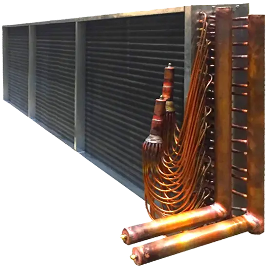
The height, length and resulting air velocities greatly figure in everything in determining the size and performance of a coil. Step # 1 in determining the size and performance of a coil is dependent upon understanding face & air velocities of air across the coil. Whether you use CCA’s coil selection program to help size the coil, or you are replacing an existing coil; the height, length and resulting velocity determine everything.

Hot Water Booster Coils

air velocities

Every coil has a specific, optimum velocity, so you want to make sure you are within 30% (+ or -) of that number. For example, booster coils have an optimum velocity of 800 ft/minute. That means that you can drop your velocity to 600 ft/minute, or conversely, increase the velocity to 1,000 ft/minute. The duct velocities are almost always higher, which means that you will need to transition to a larger coil. Try to get to as close to 800 ft/minute as possible, while sizing your coil to make the transition as easy as possible. Everything with coils is a balancing act.

Hot Water & Steam Coils

Like booster coils, hot water and steam coils should also have face velocities at approximately 800 ft./minute. Both steam & hot water coils have only sensible heating, which is why their face velocities can be the same. Face velocities ultimately control the coil’s cost, so 800 ft./minute really is a heating coil’s “sweet spot”.

If you are purchasing an air handler unit, oftentimes the heating coil is smaller than the cooling coil because the face velocities on heating coils can exceed those of cooling coils. Due to water carry-over, cooling coils cannot exceed 550 ft/minute, while heating coils only deal with sensible heat.

Chilled Water & DX Coils

Due to the limited face velocities of cooling coils, your choices are more limited. With cooling coils, your face velocity must be somewhere between 500 ft./minute-550 ft./minute. Remember that when dealing with cooling coils, you are dealing with both sensible and latent cooling, so the coil is wet. When you exceed 550 ft./minute, water carry-over occurs past the drain pans.

If you are purchasing an air handler unit, you probably will not have worry about the coil’s face velocity as most coils come pre-sized at the acceptable face velocities. Fan coils also come pre-sized with the correct CFM’s. However, if you are replacing an existing cooling coil, the face velocity must remain at or below 550 ft/minute!!

 Air Stratification Across The Coil

Air does not travel equally across the face of a coil. If you were to divide a coil into (9) equal sections, like a tic-tac-toe board, you would see a high percentage of air travelling through the center square, rather than the corner squares. In a perfect air flow scheme, 11% of the air would travel through each of the 9 squares, but that is not what happens. Because more air travels through the center of the coil, you want to avoid putting a fan too near the coil. Due to central air flows, most systems are draw-thru, rather than blow-thru. This is also why you want to avoid installing your coil near any 90 degree angles/turns in the ductwork. Avoid any situations that contribute more than the “natural” air stratification to help ensure your coil is at maximum efficiency.

In some situations involving cooling coils, you will have water carry-over even when the coil is sized correctly. How can this happen? Think about the tic-tac-toe board again. Air velocities are exceeding 700 ft./minute in the coil’s center, while the corners are around 300 ft./minute. This cannot and will not work.

Coils do not have any moving parts. They simply react to the air across the outside of the coil and whatever is running through the inside of the coil. Coils are 100% a function of your entire system, as well as the installation in general.

Capital Coil & Air is here to help with any coil selections that will help avoid costly missteps that lead to wasted time and money. Call us on your next project, we greatly look forward to working with you!

RELATED POSTS

Chilled Water, DX (Expansion) Coils & Moisture Carryover

Tips on Hand Designation & Counter-flow

Coils and Counter-flow: 5 Common Questions


Why Cooling Coils Need to Be Replaced
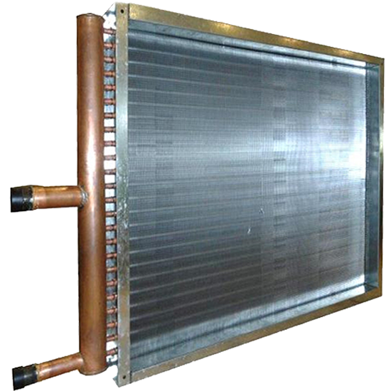
In theory, properly engineered and maintained cooling coils should deliver 20+ years of service life. In practice, most coils are replaced prematurely. The root causes are typically operational neglect, environmental exposure, improper application, or design limitations. Below are the three primary drivers of early replacement, along with technical context.


1. Increased Air Resistance from Coil Plugging

Cooling Coils

Failure Mechanism:

Airborne contaminants (dust, pollen, fibers, grease aerosols) penetrate beyond the fin surface and embed deep within the coil core. Once lodged between fins and tubes, they cannot be fully removed by routine air-side cleaning.

Primary Causes:

  • Poor filtration

  • Irregular filter replacement

  • Lack of annual coil cleaning

  • High-particulate environments

Performance Impact:

  • Increased air-side static pressure

  • Reduced airflow (CFM)

  • Decreased heat transfer 

  • Reduced system capacity and efficiency

Plugged cooling coils often force the fan to operate outside design conditions, increasing energy consumption while lowering cooling output.


2. Freeze Damage

https://www.resideo.com/us/en/-/media/Resideo/Corporate/Media%20Images/Featured%20Articles/120121/cracked-pipe_850.jpg?h=567&hash=607EE03C7CC57A4AC0E0DCCC6025A398&rv=9d8b4e00150d48e49dbc73a3291c6451&w=850
 

Failure Mechanism:

Water trapped in coil tubes expands during freezing, generating internal pressures sufficient to rupture copper tubes.

Why It Happens (Even When Dormant in Winter):

  • Circuiting designs that prevent full drainage

  • Drain connections positioned above low tubes

  • Lack of glycol protection

    broken return bends
  • Inadequate winterization procedures

Consequences:

  • Multiple hidden leaks

  • Thinned tube walls due to pressure expansion

  • Progressive failures after initial repair

  • High risk of recurring leaks

Once a coil experiences extensive freeze damage, repair becomes unreliable. The metallurgical integrity of the tubes is compromised, making replacement the only durable solution.


3. Corrosion

https://static.wixstatic.com/media/ea3647_d85a052e6f8a4b5ab1c1d0555c623a28~mv2.jpg/v1/fill/w_1000%2Ch_750%2Cal_c%2Cq_85%2Cusm_0.66_1.00_0.01/ea3647_d85a052e6f8a4b5ab1c1d0555c623a28~mv2.jpg
Corrosion occurs on both the air side and the fluid side, often simultaneously.

Air-Side Corrosion

  • Salt-laden atmospheres (coastal or industrial)

  • Hydrogen sulfides (e.g., wastewater treatment facilities)

  • Chemical exposure in manufacturing environments

Visual Indicator:

A white ring around the tube-to-fin interface. This indicates loss of mechanical bond and reduced thermal conductivity between tube and fin.

Effects:

  • Reduced heat transfer

  • Loss of tube/fin contact

  • Core blockage from corrosion byproducts

  • Elevated air pressure drop

Water/Refrigerant-Side Corrosion

  • Raw, untreated water

  • High mineral content

  • Improper water chemistry control

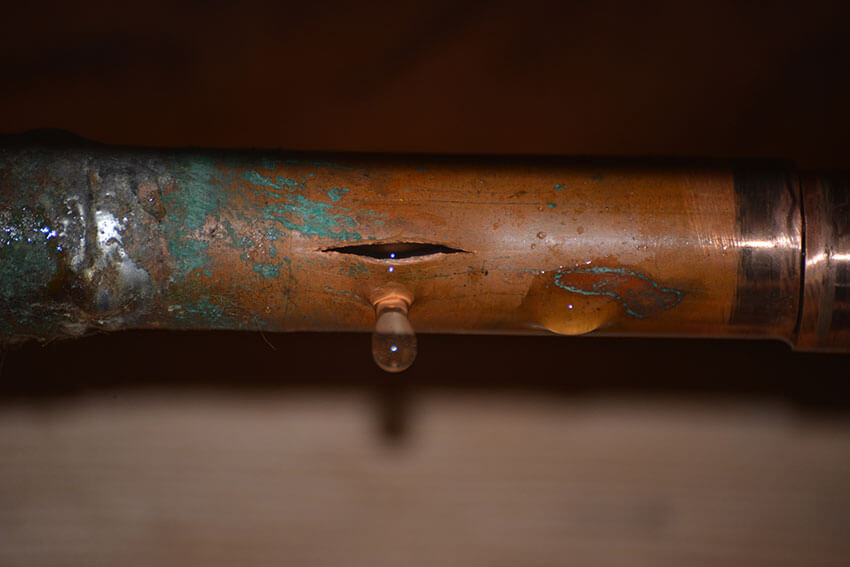
Internal corrosion weakens tube walls and leads to pinhole leaks, particularly in copper tubing exposed to aggressive water conditions.


Key Takeaway

Cooling coil replacement is common—but preventable. Most failures are not random; they are the result of design limitations, environmental exposure, or maintenance gaps. Replacing a coil without diagnosing the root cause often guarantees another premature failure.

If longevity, efficiency, and reliability matter, the solution isn’t just replacement—it’s engineered improvement.


RELATED POSTS

OEM Replacement Coils: Repair or Replace


Looking For A Trane Replacement Coil

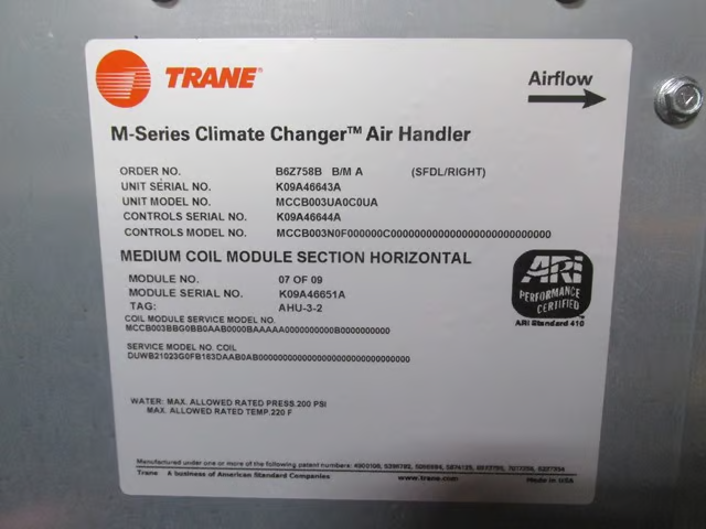
If you need Trane replacement coil within a Trane system, but aren’t sure about the dimensions or decoding the model #, send this to Capital Coil & Air for pricing. On most Trane AHU’s, the AHU model #, as well as the coil or “part #”, is listed as “Service Model No Coil”. If you see this, send it over, and the sales team at Capital Coil will handle the rest. Great pricing with the ability to be built as fast as is needed!Trane replacement coil


Top 5 Reasons Commercial HVAC Coils Prematurely Fail

Capital Coil & Air has come across virtually every scenario over the years in which a commercial HVAC coil had to be prematurely replaced, and we have since created an easy guide targeting the main reasons HVAC Coils prematurely fail.

  • Coil Plugging: If you are not changing filters and/or your commercial HVAC coils are not properly cleaned in a timely manner, your coil will actually begin to act as a filter. When dirt builds up on the coil, that blockage prevents heat transfer and can cause an approximate 20% to 40% drop in performance. Dirt adds to the coil resistance and can be a primary cause for your coil to fail prematurely.
  • Vibration: When your HVAC coils are installed near a moving piece of equipment, vibration can occur and cause leaks. You can tell if vibration is the main cause if leaks are near the tube sheet and look like they are slicing through the tube. If/when that happens, the coils should be isolated from the rest of the system to prevent vibration from causing damage. One way to combat this is by oversizing the tubesheet holes, but many manufacturers will not do this. Condenser Coils are usually the most common victims of vibration.
  • Corrosive Environment: This applies to both the air in the environment and inside the tubes. For instance, if there is a corrosive element in the air, it will eat away at the copper tubes; whether you have 0.020” wall or 0.049” wall. This is very common in coastal areas where there may be salt in the air. To keep the costs down from going to a stainless steel or cupro-nickel coil, we usually suggest coating the HVAC coils. Coatings are almost always within your budget, and its application will only add about a week to the overall lead time. Steam condensate and untreated water can cause corrosion within the tubes of HVAC coils as well. If you have a steam coil that has failed before the one year warranty, there’s a great chance that corrosive agents are in the steam, and it’s eating away at the copper tubes.
  • Freeze-Ups: Most people think that when HVAC coils freeze, the water or condensate laying in the coil freezes into ice and it expands causing the tubes to bulge and eventually spring leaks. What really happens is that the coil will freeze in multiple areas simultaneously, and it’s the pressure between these areas that cause the tubes to swell and eventually burst. These are very easy to spot as the leaks will run the length of the tube rather than around the tube.  ALSO be very careful when considering “freeze-proof” coils!  If you remove 5-6 inches from the fin length to make the “freeze-proof” application fit, your coil’s performance will suffer considerably. 
  • System Design: You would be amazed to learn how many HVAC coils were never designed properly for their systems. If there is a design problem, replacing the coil will only waste time and money; while you have done nothing other than duplicate the previous problem. A little known fact in the replacement market is that a high percentage of all our projects are because the coils were built incorrectly or were never designed correctly in the first place. In some cases, owners attempt to improve the coil’s performance by adding additional rows. Most however do this without taking into account the air pressure drop or fluid pressure drop that comes with it.

When dealing with an HVAC coil manufacturer, try to partner up with one who will walk you through the engineering and explain it along the way. Capital Coil & Air has well over a decade of experience and can help you diagnose whatever problem that you are experiencing correctly the first time. We look forward to working with you on your next project!

RELATED POSTS

Four Things That You Need When Buying Replacement Coils

Replacement HVAC Coils: 10 Common Ordering Mistakes

Coil Costs: What Will Make Your HVAC Coils More Expensive?


Different Types of Steam Coils

There are two types of steam coils:  standard steam coils, which are used in most reheat applications, and steam distributing coils, which are used in applications where the entering air temperature is below 40 F degrees.  Many times, this type of coil is also known as a “non-freeze” coil, but that name is misleading because in reality, there is no such thing as “non-freeze”. 

Standard Steam

Standard steam coils operate a lot like hot water coils, but the construction is very different even if the coils appear to be constructed the same.  The supply and return connections are often on the same end like a hot water coil.  But, steam is very different than hot water, and the coil must be built for and circuited for steam.  Keep in mind that steam is always more erosive than hot water.  The brazing and tube wall thickness must account for steam. ALWAYS remember that even low pressure steam is more erosive than hot water, and a steam coil needs to be built accordingly.

Steam Distributing (Non-Freeze)

Steam distributing coils are a completely different type of coil because they are constructed as a tube within a tube. Every place that you see an outside tube or header, there is an inside tube and header that you can’t see. The steam on the inner tube keeps the condensate in the outer tube from freezing.  The purpose of the Steam Coiloriginal coil design was to distribute the steam evenly along the length of the coil and to eliminate any dead spots on the coil.  A byproduct of this coil was also found.  The coils didn’t freeze nearly as easily as the standard steam coil, so the coils became known as “non-freeze”, which as mentioned, is not completely accurate.  Any coil can freeze under the right conditions, but, this design is what needs to be used when the entering air is under 40F degrees!!! 

Steam Coil Design

Steam coil designs can be very tricky.  Steam coils are totally a function of the system and installation, while other coils operate more independently of the system.  There needs to be correctly designed traps, and they need to be installed in the correct place and depth in the system.  Often, vacuum breakers are also needed in the system.  The piping must also be installed correctly to make sure the steam is entering the coil and not the condensate.  Even with all of those factors, you’ll need a correctly designed steam coil that matches the steam pressure, length of the coil, and the entering air temperature.  Coils can freeze easily.  Coils can be too long in length and the steam cannot travel the length of the coil and distribute evenly.  Condensate can easily be trapped somewhere in the coil, and the result is water hammer. 

Capital Coil & Air has years of experience designing steam coils, and is here to answer any questions and help to design the right coil for your project! 

Related Topics

Frozen Steam Coils: How to Prevent it!

Commercial Steam Coils; Lengths & Controls

HEATING SEASON WILL SOON BE UPON US


Chilled Water Coils – Circuiting Made Easy

Chilled Water Coil

Circuiting chilled water coils is one of life’s great challenges in the coil business. You’re bound to run across folks with years of experience in the industry that can not effectively explain this concept. While not the most exciting of subjects, the necessity of circuiting chilled water coils can not be overstated. Capital Coil & Air has attempted to simplify the idea of circuiting as much as possible.

For starters, circuiting chilled water coils is ultimately up to the performance of those coils. Circuiting is really a balancing act of tube velocity and pressure drop. In other words, think of a coil as a matrix. Each coil has a specific number of rows, and a specific number of tubes within each row. For example, a chilled water coil might be 36 inch fin height and 8 rows deep. The coil has 24 tubes in each row, and multiplied by 8 rows, there is a total of 192 tubes within the coil. While you can try to feed any number of tubes, there are only a few combinations that will work.

    • Feeding 1 tube – you will be making 192 passes through the coil, which will essentially require a pump the size of your car to make that process work.
    • Feeding 2 tubes – equates to 96 passes, and your pressure drop will still be enormous.
    • Feeding 3 tubes – 64 passes, which is still too many.
    • Feeding 4 tubes – See above.
    • Feeding 5 tubes – Impossible as 5 does not divide evenly into 192 (passes).
    • Feeding 6 tubes – Still constitutes far too many passes, which again leads to additional pressure drop.
    • Feeding 7 tubes – Same rule for feeding 5 tubes.
    • Feeding 8 tubes –  Same rule for feeding 6 tubes.
    • Feeding 24 tubes – This feed consists of 8 passes, which is in the ballpark, and with a pressure drop you can live with.
    • Feeding 32 tubes – 32 tubes will see 6 passes. You might see a slight decrease in performance, but it’s off-set by a continuously better pressure drop.
    • Feeding 48 tubes – The magic combination, as 4 passes typically elicits the best performance and pressure drop simultaneously.


Rule #1: The number of tubes that you feed must divide evenly into the number of tubes in the chilled water coil.

Rule #2: The chilled water coil must give you an even number of passes so that the connections end up on the same end.

Rule #3: Based on the number of passes, you must be able to live with the resulting pressure drop. Acceptable tube velocity with water is between 2 and 6 ft. per second.

You’re bound to run into different terminologies depending on the manufacturer. More times than not, the different verbiage confuses more than it clarifies. However, understanding the basic tenets of chilled water coil circuiting will remove much of the perceived difficulty.  

Related Posts

Coils and Counter-flow: 5 Common Questions

Chilled Water Coils & Moisture Carryover

Top 10 Things You Need to Know About Chilled Water Coils