What Is Meant By A “Bank” Of Chilled Water Coils

For those that work with HVAC installations on a regular basis, you have run across the problem of needing to install new chilled water coils in very tight, confined areas. The coil is too big to fit in the Chilled Water Coilselevator, and/or the HVAC room is so small that you are likely to damage the coil simply by moving it. As a solution to this challenge, chilled water coils are often installed in “banks” of coils. You are most likely to see this configuration in Air Handler Units, as well as “built-up” systems. Due to face velocity limitations across the coil, you will need larger coils in order to meet your required face area. With this in mind, there are a few specific reasons why you want to avoid having a single, large coil in one of your units.  Starting with the obvious: larger coils are much more difficult to transfer and install. This is especially true for older buildings, where the rooms were essentially built around the HVAC system.

As you’ve probably experienced, some of these areas can barely fit a single person, so installation – if even possible – is a logistical nightmare. Also, the larger the coil, the easier it is to damage during transport to the jobsite. To avoid these issues, simply break down the single, larger coil into smaller coils. When piped together, those smaller coils are stacked into “banks” of coils in the system. If installed correctly, this “bank” should have the same performance as the larger, single coil.

Casing

There are many different casing options available, but “stackable” flanges are required for heavy chilled water coils that are “banked”. The flanges are often inverted inward and down to give added strength to the casing, which is needed due to the fact that another coil of equal weight will be stacked on top of it. When ordering coils in a “bank” configuration, be sure to let the manufacturer know that they will be “stacked”.

Many engineers also use stainless steel casings on chilled water coils. While more expensive than traditional galvanized steel, stainless steel protects against excessively wet coils and/or corrosive elements in the airstream. Keep in mind that the majority of coils fail because of old age and its casing, as opposed to failure with the coil’s core. With that in mind, doesn’t it make sense to select heavy-duty stainless steel casings that are more durable and meant for stackable installations?

Drain Pans & Water Carryover

Water Coils

All chilled water coils must be sized so that the face velocity across the coil does not exceed 550 ft/minute. Water on the outside of the coil is carried away from the coil’s leaving air side in an arc, while water in the highest point of the coil is carried further down the unit or ductwork. “Stackable” coils often require intermediate drain pans under each coil to catch the excess water carryover. Each coil in a bank requires its own drain pan, as a single, large pan under the bottom coil is not enough.

Circuiting/GPM

If all of the coils in a “bank” are of equal size and handling the same CFM, then the GPM of each coil will also be the same.

Always feed the bottom connection on the supply header on the leaving air side of the coil. This ensures counter air and water flow. This also prevents the coil from short circuiting because the header fills first and circuits all of the tubes equally.

Designing Banks Of Coils

Almost all coil “banks” perform more efficiently if you design something more square in shape, as opposed to long and/or high. In a “bank” of coils, you may find that one coil has points of 300 ft/minute, with other points at 800 ft/minute. Scenarios such as this will cause water-carryover! You generally want to be as close to 550 ft/minute as possible in order to allow equal airflow distribution across the face area of the coil.

Anytime you are designing and/or building coils, work closely with the manufacturer as an added resource to ensure that you are getting the ideal solution for your HVAC system. Capital Coil & Air works on similar jobs such as these daily, and we welcome the opportunity to work with you in whatever capacity is needed.

RELATED POSTS

Top 5 Reasons HVAC Coils Prematurely Fail

Coils and Counter-flow: 5 Common Questions

Chilled Water Coil Circuiting Made Easy


TOP 10 FAN COIL FAQ’S

1. A fan coil is among the easiest units to understand in the HVAC industry.  Basically, there is a small forward curved fan, a coil, and sometimes a filter.  They are all direct drive units. Click HERE to see Capital Coil’s full Fan Coil Product Lineup.

2.  Fan coils run from 200 CFM to 2200 CFM, which is 0.5 ton through 5.5 tons.  Anything larger than these sizes requires a belt drive unit…which is really a full fledged air handler.

3.  The thing that differentiates fan coil units is where and how they are going to be installed.  Is the unit going to be hidden above the ceiling or maybe in a closet?  Or is it going to be exposed so that everyone can see it?  Will it be ducted or will it just pull air from the space where it’s located?  These are things that determine the configuration of the unit and which style of unit to choose.  But, every unit has 3 things in common:  fan, coil, and sometimes a filter.

Fan Coils4.  Some units have (2) coils.  One for heating and one for cooling.  Obviously, there is a separate supply and return connection for each coil and these units are known as 4 pipe fan coils.  Many units only use the same coil for both heating and cooling and these units are 2 pipe fan coils.

5.  Units are either horizontal or vertical depending on the orientation and flow of the air.  A typical fan coil in a hotel room is a vertical unit with a mixture of air coming from outside and the air recirculating in the room.  The air enters at the bottom of the unit and is drawn upward through the fan.  This makes the unit a vertical style.  Many units are horizontal with the air entering at the back of the unit and traveling horizontally through the unit.

6.  Almost all fan coils are 3 speed or infinite speed settings based on the controls.  The high speed gives you more BTU’s, but more noise too.  Because the unit is direct drive, when you dial down the speed, you also dial down the performance.

7.  Coils in the units tend to be 3 or 4 row deep coils.  3 row is typically used the most, but if you need the extra performance, 4 row is the way to go.  Performance is always governed by the cooling aspect.

8.  Fan coils sometimes have short runs of duct work and there is static pressure on the unit.  Static pressure reduces the amount of CFM and BTU’s that the fan coil can give you.  This is true of both horizontal and vertical units.  Most performances listed on charts that you will see are static free performances.

9.  The control systems for fan coils are often more complicated and more expensive than the units themselves.  There are balancing valves, isolation valves, unions, y-strainers, p/t plugs, air vents, ball valves, thermostats, condensate float switches, and disconnects.  Capital Coil & Air can do this at the plant, but it is much cheaper and easier to do it at the installation. 

10.  Just describe your installation requirements to a sales engineer at Capital Coil & Air and they will guide you to the right design and configuration of the unit for you.  It requires only a phone call or e-mail! We look forward to working with you!


RELATED POSTS

Top 10 Chilled Water Coil Facts

Light-Duty Commercial Belt Drive Air Handlers

Top 10 Questions You SHOULD Be Asking Your Coil Supplier


Chilled Water Coils – Circuiting Made Easy

Chilled Water Coil

Circuiting chilled water coils is one of life’s great challenges in the coil business. You’re bound to run across folks with years of experience in the industry that can not effectively explain this concept. While not the most exciting of subjects, the necessity of circuiting chilled water coils can not be overstated. Capital Coil & Air has attempted to simplify the idea of circuiting as much as possible.

For starters, circuiting chilled water coils is ultimately up to the performance of those coils. Circuiting is really a balancing act of tube velocity and pressure drop. In other words, think of a coil as a matrix. Each coil has a specific number of rows, and a specific number of tubes within each row. For example, a chilled water coil might be 36 inch fin height and 8 rows deep. The coil has 24 tubes in each row, and multiplied by 8 rows, there is a total of 192 tubes within the coil. While you can try to feed any number of tubes, there are only a few combinations that will work.

    • Feeding 1 tube – you will be making 192 passes through the coil, which will essentially require a pump the size of your car to make that process work.
    • Feeding 2 tubes – equates to 96 passes, and your pressure drop will still be enormous.
    • Feeding 3 tubes – 64 passes, which is still too many.
    • Feeding 4 tubes – See above.
    • Feeding 5 tubes – Impossible as 5 does not divide evenly into 192 (passes).
    • Feeding 6 tubes – Still constitutes far too many passes, which again leads to additional pressure drop.
    • Feeding 7 tubes – Same rule for feeding 5 tubes.
    • Feeding 8 tubes –  Same rule for feeding 6 tubes.
    • Feeding 24 tubes – This feed consists of 8 passes, which is in the ballpark, and with a pressure drop you can live with.
    • Feeding 32 tubes – 32 tubes will see 6 passes. You might see a slight decrease in performance, but it’s off-set by a continuously better pressure drop.
    • Feeding 48 tubes – The magic combination, as 4 passes typically elicits the best performance and pressure drop simultaneously.


Rule #1: The number of tubes that you feed must divide evenly into the number of tubes in the chilled water coil.

Rule #2: The chilled water coil must give you an even number of passes so that the connections end up on the same end.

Rule #3: Based on the number of passes, you must be able to live with the resulting pressure drop. Acceptable tube velocity with water is between 2 and 6 ft. per second.

You’re bound to run into different terminologies depending on the manufacturer. More times than not, the different verbiage confuses more than it clarifies. However, understanding the basic tenets of chilled water coil circuiting will remove much of the perceived difficulty.  

Related Posts

Coils and Counter-flow: 5 Common Questions

Chilled Water Coils & Moisture Carryover

Top 10 Things You Need to Know About Chilled Water Coils


Condenser Coils Failing? Here’s probably why….

Did you recently turn on your DX systems only to find your Condenser Coils are not working?  Simple fix right?  Unfortunately, no.  If you get lucky, you can send us the model number of the unit, and there’s a great chance we’ve already built it.  In the case that we do not have that model number on file, you have two options.  You can go back to the OEM, wait (5) months for a part and pay through the roof.  Or you call Capital Coil, and we’ll walk you through the engineering it takes to replace a condenser coil.                                                                      Condenser Coils

Very rarely do condenser coils ever freeze so the first thing you’re going to want to know is if your coil died of corrosion, old age, or possibly vibration.  Old age is obviously preferable because with a few easy dimensions, we’ll have enough to price up your duplicate coil.  Condenser coils are usually outside and are easily accessible for measurements and digital pictures.  With just the size, the rows, and fins/inch, you can get a price.  And digital pictures of the headers and return bends will give us a good idea of the circuiting and sub-cooler circuits. 

If the coil has been eaten away by corrosion, it was an improper design to begin with.  Most people don’t know that salt in the air will ruin aluminum fins within a year or two.  There are two ways to combat this.  The first option is to make the switch to copper fins and stainless steel casings.  While this will extend the life of your coil considerably, most people are not too happy about the additional cost over aluminum fins.  The second option is to use a coating.  Coatings are the much more popular choice.  They are a fraction of the cost as copper fins and only add (1 – 2) weeks to your lead time. 

When your HVAC coils are installed near a moving piece of equipment, vibration can occur and cause leaks.  The area where these leaks occur is very important and will clue you in to if the problem is vibration.  If they are near the tube sheet and look like they are slicing through the tube, the coils should be isolated from the rest of the system to prevent vibration from causing damage.  One way to combat this is by oversizing the tubesheet holes, but many manufacturers will not do this.  Condenser coils are usually the most common victims of vibration.

The last concern is with cleaning condenser coils.  Since condenser coils see outside air almost exclusively, they need to be cleaned more than other coils.  The reason for this is most condenser coils have fin spacing of 12-20 fins/inch.  With fins that tight together, the coil can and will act like a filter.  And when the coil is clogged up, the performance suffers greatly.  Recently, we’ve been getting more and more calls about using a heavier fin thickness.  This is to help with high pressure cleaning and corrosive cleaning agents. 

When dealing with an HVAC coil manufacturer, partner up with one who will walk you through the engineering and explain it along the way. Capital Coil & Air has well over a decade of experience and has seen every issue to make sure your everything from the quote to the installation go smoothly! Give us a try on your next project!

RELATED POSTS

Top 5 Reasons HVAC Coils Prematurely Fail

You should never have to worry about performance on replacement coils. Well… almost never!

Repair or Replacement HVAC Coils?


OEM Replacement Coils: Repair or Replace

When considering OEM replacement coils, there are multiple reasons why coils can fail prematurely. Sometimes, OEM Coils simply freeze and can never be repaired. Other times, the coil was selected incorrectly, which in turn, made the coil significantly underperform. Many times, there is substantial corrosion or something else in the system that causes the coil to fail. However, most coils, when selected correctly, and in systems that are properly maintained, can last anywhere from 10-30 years!  10-30 years is also a pretty wide range, and there are many variables in how long you can expect a coil to perform. Factors, such as ongoing maintenance, air quality, and water/steam quality all have an effect on a coil’s lifespan.

OEM Replacement Coils

Reasons Why Coils Fail Of Old Age

  • While the coil’s tubes are considered the primary surface, 70% of all coil performance is performed by the finned area on a coil, which is known as the secondary surface. The fin/tube bond is easily the most important manufacturing feature in any coil. Without the bond between the tubes and fins, the coil could never properly function. Like all things however, over time the fin/tube bond becomes less efficient with constant expansion and contraction. While the construction of the coil, as well as the fin collars, does not allow the fins on the coil to move, that fin/tube bond naturally weakens a coil’s life over time after installation. Because of this, it is not a stretch to say that a coil is easily 30% less efficient after (20) years.
  • Cleaning coils often pushes dirt to the center of the coil, and this occurs even more so on wet cooling coils. Just remember that coils can become great air filters if not properly maintained. The BTU output of any coil is in direct proportion to the amount of air going through the coil. If you decrease the CFM by 20%, you are also decrease the BTU’s by 20%!
  • Cleaning agents often corrode aluminum fins. Since every square inch of fin surface matters in performance, corrosion of the fin surface is always detrimental to the coil’s performance.
  • Many times, there are coil leaks simply because of old age. No coils are immune to erosion. You might find the brazing in the tubes, as well as the brazing in the header/tube connections failing over time. Steam can be both erosive and corrosive under higher pressures. Water travels through the coil at 2 – 5 ft/second, so erosion is an enormous part of coil failure, regardless of how well-maintained. Erosion is always there, whether you realize it or not.
  • Water/steam treatment and the corrosive effects of bad steam/water can all be causes of coil failure…which then necessitates the need for a reliable manufacturer for OEM replacement coils.

So What Is The Solution?

Some coils can last 5 years, and some coils can last 30 years. As you have read, there are numerous factors that contribute to a coil’s life. In the end, there will most likely have been multiple attempts to repair that coil to make it last as long as possible. The depressing news is that most of these “Band-Aid” attempts do not work well. The most likely outcome is that you are buying a new coil anyway, so why waste the time and money on a temporary solution?

Coil failure is a “pressure event”, which is a fancy way of saying that a coil is leaking. We’ve listed some of the most common repair methods that you are likely to come across:

  • Drop leaking tubes from the circuit: Keep in mind however that every dropped tube reduces the coil’s performance by triple the surface area of the tube that is dropped. Again, while ok in the short-term, this is simply another “Band-Aid” fix. Over time, your energy costs will rise exponentially, and you will probably end up buying a new coil anyway.
  • Braze over the existing braze: As mentioned above, erosion has caused the original braze to fail, so all that you are really doing is pushing the pressure to another braze, which will then begin to fail as well.
  • High Pressure Cleaning: This method bends the fins, further restricts the airflow, and pushes dirt more to the center of the coil, which can never be adequately cleaned.

The real reason why coils need to be replaced rather than repaired is due to energy costs. If your coil is not operating near desired levels, you’ll need to increase the energy to make it work at its peak performance. Energy increases might be slight at first, but they are guaranteed to continue to rise over time. For example:

  • Somebody adjusts the fan drive for higher speeds, higher CFM’s and higher BTU’s.
  • Someone adjusts the boiler; the water and steam temperatures are higher.
  • Someone adjusts the chiller (1) degree higher for colder water to the chilled water coil.

Whichever method is used, performance begins to suffer and adjustments to the system occur. These adjustments cost energy efficiency and ultimately, money!

If you have ever experienced repairing a coil, then you know it is labor intensive and typically will not work as a permanent solution. With very few exceptions, repairs should be seen as nothing more than temporary until you’re able to replace that coil!

Capital Coil & Air has seen every “repair” method used, as well its inevitable outcome, so instead of putting yourself through that, call Capital Coil and allow us to be your coil replacement experts.

RELATED POSTS

Is Your Quick-ship Shut Down When Needed Most??

Four Things That You Need When Buying Replacement Coils

Replacement HVAC Coils: 10 Common Ordering Mistakes

Top 5 Reasons HVAC Coils Prematurely Fail


Case Study: We Need These Coils on a (5) Day Quick-ship

In late June, Capital Coil received a call from a Trane office in Ohio regarding quick-ship availability. One of Trane’s top customers had an urgent need for (12) large chilled water coils with stainless steel casing. The problem/hurdle that they were encountering was that they needed all (12) coils to be built and ship out of the factory in (5) business days. Completion of the whole project was 100% contingent on them receiving the coils in their specified time-frame. An additional complication was the fact that July 4th was the following week, and they needed to have the coils ship prior to the holiday.

Trane shopped the project around to different manufacturers, but not one could guarantee to ship in (5) days. Some manufacturers waffled and claimed that they could have them built in (6) or (7) days, but not one could guarantee to ship in (5) days. A sales rep in that same Trane office, who had worked with Capital Coil previously, suggested that his co-worker reach out to us to see what we could do. After speaking with Trane’s project manager, we immediately contacted our head of production to make sure that we had the capacity to complete all (12) coils in the required (5) days. She assured us that we had the materials and manpower on-hand to get them all built and ship on time. We agreed to accept the project and began work on the coils immediately.

Due to the size of the project, as well as it’s time-sensitivity, we had multiple calls daily with our factory to ensure that everything was proceeding on schedule. We then gave Trane daily status updates, so they were constantly informed of everything from the brazing of the coils to entering the final testing phase. Chilled Water Coil

As promised, all (12) coils were built correctly and shipped out in the required (5) days. Our logistics team was then in constant communication with the freight company to make sure that the delivery was on schedule. And just like during the production phase, we passed daily tracking updates along to Trane, so they knew where their coils were at all times and when they could expect delivery. All (12) chilled water coils arrived on July 3rd with zero freight damage, and the project was completed on time!

A company as large and influential as Trane can have their coils built by anyone, but Capital Coil was the only manufacturer that could guarantee to have their coils built and shipped by a required date. Additionally, in working so closely with Trane throughout the whole process, they were kept up-to-date in real time from the start of production to final delivery.

Capital Coil offers a level of service that you won’t get with other manufacturers. When we guarantee to ship by a certain date, we stand by that guarantee, or you do not pay!


Trane’s project manager’s comments to Capital Coil upon completion/delivery:

“This will help us get a jump on this project prior to the big event taking place next week! 

I will make sure to share your information with others across our great lakes region about our experience with your company, so that they know we have THIS option to go to for our coil needs. THANK YOU ALL!!”


How to Make Sense of Heating Coils

Various winter storms have already ripped through multiple parts of the country necessitating the obvious need for working heating coils!!  With conditions such as these, emergencies with your HVAC systems are almost inevitable. THIS is precisely when you need your coil supplier to have the speed and flexibility to be able to tackle whatever emergencies arise.Steam Coil

Of all the types of HVAC coils available, heating coils are probably the easiest to select and understand. Capital Coil has listed the three most common types of heating coils that you are likely to come across.

Hot Water Coils

When looking at a water coil, the first thing to remember is that it is in effect “dumb”. In other words, water coils do not know the temperature of the water moving through it. While standard HVAC water coils are mostly constructed in the same design, the number of rows contained within the coil is a key differentiator in determining if the coil is hot water or chilled water. 99% of all hot water coils are (1) or (2) rows based on performance requirements. The “Delta T” between the entering air temperature and the hot water temperature is very large. As a result, you only need a coil with (1) or (2) rows to do the job. Face velocities across the coil can be anywhere from 600 to 1,200 FPM (feet/minute), while water velocities are usually 2-4 FPS (feet/second). As a result, you will always end up with a (1) or (2) row coil with somewhere between 8-14 fins/inch.

Booster Coils

Hot water booster coils are just another variation of the standard HVAC hot water coil.  They are always (1) or (2) rows as well, but the casing is designed for duct work installation. This basically means there is usually a 1” or 1.5” casing on all four sides of the coil. You select the proper size of the coil to make sure the air velocity across the coil is correct and simply transition the duct work to make the casing size around the coil.  Generally speaking, the size of the coil face is larger than the duct size, so you must transition the duct to make it larger. Just remember, a booster coil is nothing more than a standard hot water coil that is used for duct work installation.

There can also be a casing variation called “slip & drive”, where the coil is installed in the duct work. The coil does not have the standard casing on all four sides like a flanged coil. Capital Coil’s selection program allows you to pick either option.

Steam Coils

The real secret to any steam coil installation is to know that steam coils are much more of a product of the entire system than any other coil; meaning that other coil types are much more independent of the system.  Steam coils require numerous considerations, such as traps, pitched casing, piping flexibility, and vacuum breakers.  Steam coils are also built according to steam pressure through the tubes and headers.  2 – 50 psig is considered “low pressure” steam for coils, while 50-100 psig is considered “medium pressure”. Anything over 100 psig is considered “high pressure” steam.  An important fact to remember is that each of these categories requires a separate kind of construction with different brazing and different materials.  Additionally, almost all steam coils are (1) or (2) rows deep. Steam coils are known either as “standard” steam or “steam distributing”, but the differences are very easy to understand.  Outside air temperatures below 40˚F require that you have a “non-freeze” steam distributing coil.

RELATED POSTS 

Stock Hot Water Coils – Quick Buyers Guide

Your Goals as a Buyer of Commercial HVAC Replacement Coils

Coil Costs: What Will Make Your HVAC Coils More Expensive?


Why Are Fin Designs On HVAC Replacement Coils Important?

Replacement HVAC Coils

At first glance, fin designs on HVAC replacement coils seem about as exciting as watching grass grow. “Why would I ever care about fin designs on any coil” was probably your initial response to our question. Nevertheless, we would not dedicate a newsletter to this subject if fins were not important.

One of the primary reasons fins are so important is that you want to keep your coil as clean and maintained as possible. In order to properly maintain your coil, you need to have an understanding as to how HVAC replacement coils are constructed. While fins do not look like much, they are MUCH more complicated than what you can observe at the entering or leaving airside of the coil.

To begin, fins are responsible for a surprising 65% – 70% of the heat transfer on any coil, while tubes are responsible for the remaining 30% – 35%. Additionally, in order for your coil to work at optimum performance, you need to have a terrific fin/tube bond, (which we will discuss below).

  1. Fins are known as secondary surface, while tubes are referred to as primary surface. While this may seem counter-intuitive, the secondary surface is responsible for twice the amount of heat transfer as the primary surface.
  2. There are special dies (see picture) that stamp out aluminum or copper fins with the correct thickness, height, and depth to make the coil the correct size. For example, a coil might be 36” (height) x 96” (length) x (8) rows deep x 8 fins/inch.
    1. Fin Height: 36”
    2. Fin Depth: 12”, (8) rows deep
    3. # of fins in the coil: 768 (8 fins x 96”)
  3. Each fin has 192 holes stamped in the fin for 5/8” OD tubes (8 Rows x 24 Tubes), and each fin is identical.
  4. Each hole has extruded metal, which is more commonly referred to as the fin collar. The collars are sized to self-space the fins and allow for later expansion of the tube into the fin collar. This practice is also known as “bonding” and is essential to having your coil run efficiently/correctly.
  5. Each fin is rippled at the entering and leaving edge of the fin to help create air turbulence.
  6. Each fin is corrugated in the direction of airflow to allow for greater air turbulence. This is important to remember because turbulence creates heat transfer.

So again, what is the point of understanding the importance of fins in HVAC coils? While coils can be built with flat fins for various reasons, the vast majority of coils are built with enhanced fins. Enhanced fins help to ensure that the airflow is not running straight through the coil.

Regardless of fin type, keep in mind that HVAC coils can and will act as great “filters”. The tubes are staggered and not in-line; while the fins are designed to help break up the airflow and not facilitate an easy, straight-through air path. Dirt and/or other particles in the air get caught easily, which again, is why coils can act as great filters. Additionally, coils with more rows will usually get dirtier than coils with less rows. Lastly, chilled water or DX coils are typically wet coils, which results in them catching virtually everything in the air.

The amount of BTU’s through any coil is in direct proportion to the amount of air through the coil. For example, if you are only getting 90% of the design air through the coil, then you are only getting 90% of the BTU’s.

Coils require good filtration and periodic maintenance. If not done correctly, you’ll pay the price of higher energy costs on an inefficient coil.

By now, you have hopefully come to the realization that HVAC coils are much more complicated than they appear, and that fins are an integral part of the coil as a whole. Again, while admittedly not the most exciting topic, understanding the role and importance of fins in HVAC coils cannot be overstated. Capital Coil & Air is here to help you with any and all coil selections, and we look forward to working with you on your next project.

RELATED POSTS

Repair or Replacement Coils?

Top 5 Reasons HVAC Coils Prematurely Fail

Are You Asking Your Coil Supplier These Questions?


Frozen Steam Coils: How Do You Prevent This?

Regardless if you have steam coils or steam distributing (non-freeze) coil, you can freeze ANY coil.  When freezes happen, everyone immediately looks to the steam coil as the cause.  When in fact, there are numerous reasons that must be looked at well before the coil.

Freezes generally happen in older systems, however if your new system is not maintained properly or correctly installed, your steam coil can and will freeze.  For instance, you’d be surprised at how many times dampers are left open, controls fail, freezestats don’t work, etc.Steam Coils

In a Standard Steam or Steam Distributing Coil, a freeze-up can occur when condensate freezes within the tubes of the steam coil.  The two most common reasons for freezing steam coils are the steam trap and the vacuum breaker.  The function of steam trap is to remove the condensate as soon as it forms.  Condensate usually collects in the lowest part of the coil.  If your steam trap isn’t installed properly, that condensate will lay in the coil and it will inevitably freeze as soon as it sees outside air.  The vacuum breaker also helps clear the condensate, minimizes water hammers, and helps with uneven temperatures. This must be installed on the control valve and always above the steam trap.

Unfortunately, there are no ways to determine exactly where your steam coil will freeze.  And a common misnomer is that the condensate turns to ice and the expansion is what causes the tubes of the coil to pop.  In reality, it’s the pressure that builds up between freeze points.

Here’s couple tips in your coil design that can help prevent your standard steam and steam distributing coils from freezing:

  • Standard steam coils should NEVER see any outside air below 40 degrees.  If it does, steam distributing is the only way to go!
  • 5/8” OD Steam distributing coils over 72” long are recommended to have a dual supply
  • 1” OD Steam distributing coils over 120” long are recommended to have a dual supply
  • Make sure your steam coil is pitched if possible.  This slopes the condensate to the return connection making it easier to remove the condensate

Give Capital Coil & Air a try on your next project. Our engineering, pricing and service is the best in the industry!

RELATED POSTS

Heating Season Will Soon Be Upon Us

Commercial Steam Coils; Lengths & Controls

Types of Steam Coils


How Should Steam Coils Be Designed??

Steam coils

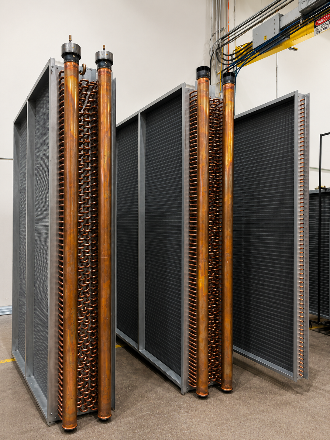
Of all of  the various types of coils, steam coils operate in the most complicated ways. They are, in effect, a product of the system and controls around the coil. If not installed correctly, steam coils simply won’t work properly.

Overview:

The object of any steam coil is to have steam enter the coil as steam and exit as condensate. In a perfect scenario, the BTU load on the coil turns steam into condensate just before it’s ready to exit the coil. Under real world conditions however, condensate usually begins to form inside the tubes almost immediately. Especially when dealing with low-pressure systems, you have to find a way to evacuate the condensate from the steam coil.
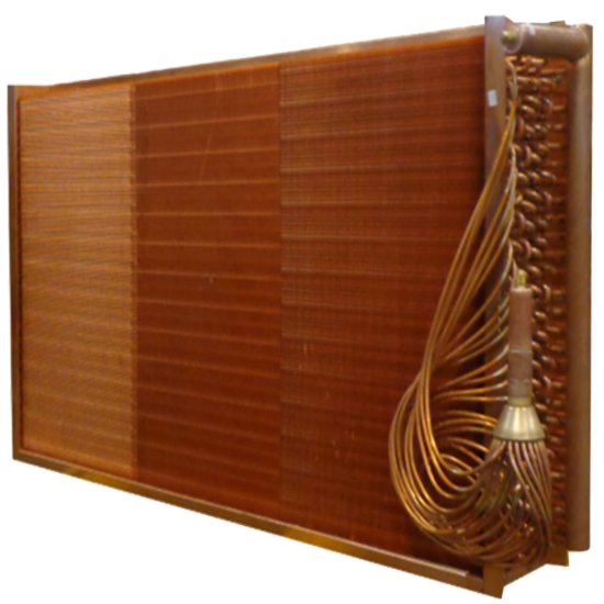
Coil Pitch

A good coil manufacturer will internally pitch the steam coil within the coil casing to force the condensate toward the outlet connection. This pitch is usually 1/8 “ per lineal foot of coil.

Coil Length

If you require steam to travel 144” and make multiple passes through the coil, then, simply put, your system will not work properly. Condensate forms too early, and it cannot escape the coil. Because of this, coils cannot be too long. A better strategy is to break one long coil into two smaller coils side by side, while feeding from both sides.

Tube Diameter:

Steam Distributing coils often have to be 1  1/8 ” diameter tubes. If the BTU load on a coil is really large, then as a result, you will generate many more Lbs./hour of condensate. If the tube diameter is too small, then the condensate, which needs to evacuate, has no place to go.

Traps:

Traps are required on steam coil systems. The traps should be “float & thermostatic” type traps and be located 18 “ below the condensate connection on the steam coil. Without this, the condensate just sits in the system without any place to go.

Vacuum Breakers

Vacuum Breakers are often installed in coil systems to remove any excess condensate that may remain within the coil.

Insulated Piping:

There is no such thing as a “Condensate” Heating coil, built as a steam coil. IT DOESN’T WORK.  However, and this happens an astounding amount of times, due to the long distances the steam has to travel from the boiler to the coil, many times, the steam will enter the coil as condensate due to the piping not being insulated.

Anything that makes condensate lay in a coil is harmful to both the steam coil and the system. You will get a “water hammer” when the system is turned on and the incoming steam just blasts against the condensate. Worse than the loud and annoying sound that produces is the fact that it just destroys the steam coil. The brazing was never designed for “water hammer”.  Also, the coils do not heat properly. Have you ever seen a long coil and run your hand down its length only to feel that the entering steam end of the coil is hot but the far end is cold? More times than not, this means that condensate is laying in the coil and not allowing the steam to properly travel the length of the coil.

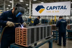
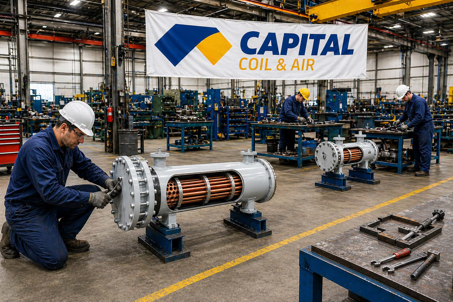
Steam Coils require a real expertise to design & build. We at Capital Coil have a long history in solving coil problems and building steam coils so that they work correctly the first time. Give us a call for your next job – you’ll be pleasantly surprised!

RELATED POSTS

Different Types of Steam Coils?

Frozen Steam Coils: How Do You Prevent This?

Steam Distributing (Non-Freeze) Coils: The Accidental Coils