When an OEM coil starts leaking or underperforming, the first question is usually:
Can we repair it, or does it need to be replaced?
The honest answer: repairs may buy time, but most are temporary fixes.
Commercial HVAC coils fail for several reasons:
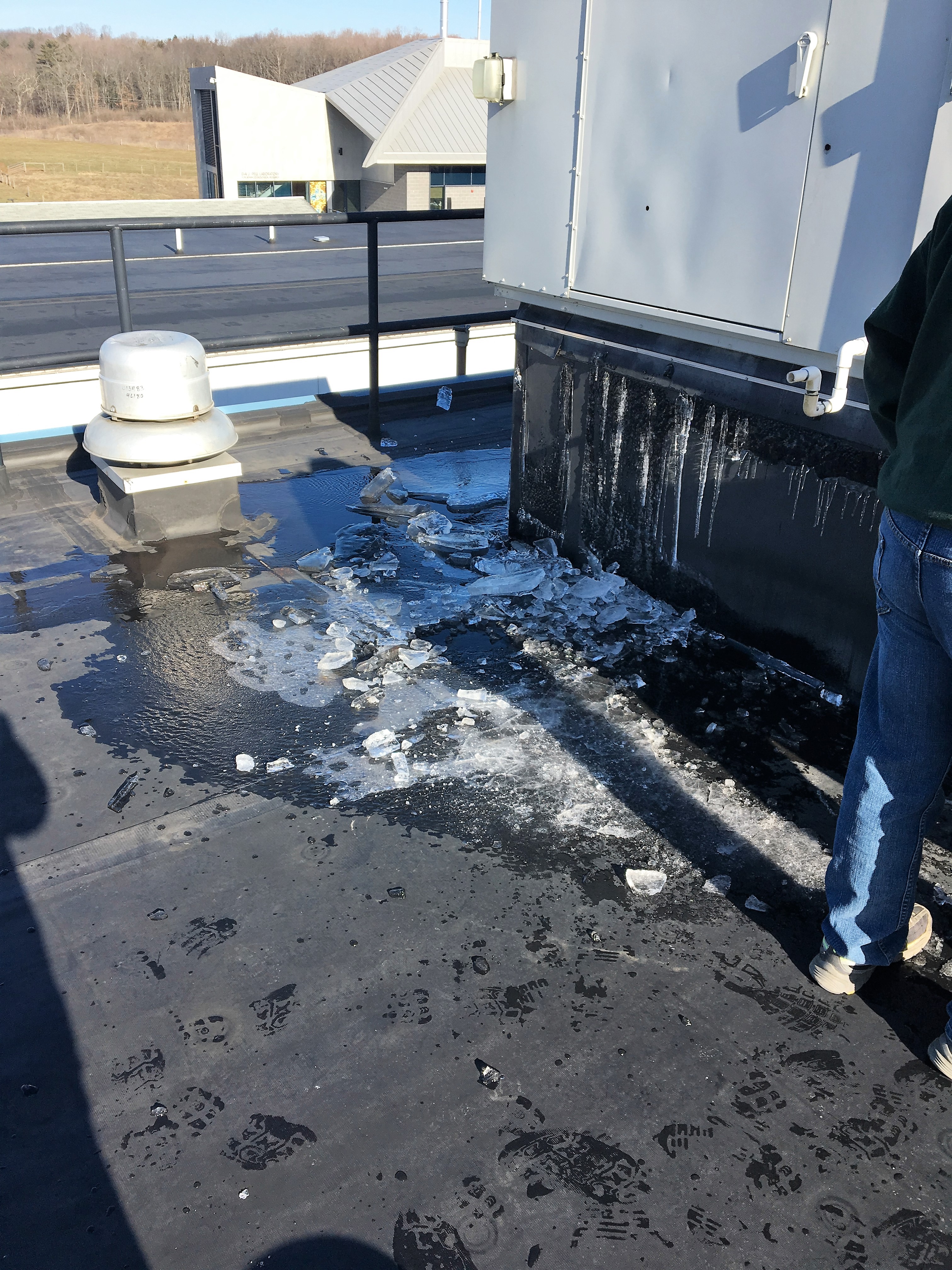
- Freeze damage
- Corrosion
- Poor water or steam quality
- Incorrect coil selection
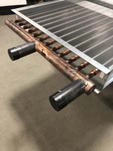
- Erosion at tube/header connections
- Loss of heat transfer efficiency over time
- Dirt, debris, and restricted airflow
A properly selected and maintained coil can last 10–30 years, but that range depends heavily on maintenance, air quality, water quality, steam quality, and overall system conditions. The issue is that once a coil starts failing, the system usually starts compensating.
That may include:
- Increasing fan speed to push more air
- Adjusting boiler temperatures
- Lowering chilled water temperatures
- Running equipment longer to meet load
Those adjustments may help temporarily, but they usually increase energy costs and put more stress on the system.
Common coil “repairs” include dropping leaking tubes, brazing over failed joints, or high-pressure cleaning. Each one comes with a tradeoff.
Dropping tubes reduces coil capacity.
Re-brazing often shifts the failure point somewhere else.
High-pressure cleaning can damage fins and restrict airflow even further.
That is why coil repair should usually be viewed as a short-term solution, not a permanent fix.
At some point, the cost of lost efficiency, repeated service calls, and system strain becomes greater than the cost of replacing the coil.
When that happens, the better long-term answer is usually a properly built OEM replacement coil that matches the original unit and restores performance.
At Capital Coil & Air, we help commercial HVAC contractors, service managers, and facility teams replace failed coils quickly and accurately, so they can get their systems back online without guessing.
Main takeaway:
A repair may stop a leak temporarily.
A replacement restores capacity, efficiency, reliability, and long-term system performance.
In short, repairs may buy time, but replacement is guaranteed to restore performance.
RELATED POSTS
Condenser Coil Failing? Here’s Why
Top 5 Reasons Commercial HVAC Coils Prematurely Fail
 Were you aware that
