Data Centers Are Reshaping the HVAC Supply Chain
If you’ve recently tried to purchase a replacement HVAC coils, you’ve likely noticed longer lead times, fewer quick-ship options, and rising costs. The primary reason? The explosive growth of data centers.
Driven by cloud computing, AI, and digital infrastructure expansion, data centers are consuming massive amounts of HVAC equipment and cooling components. As manufacturers dedicate more production capacity to these large-scale projects, replacement coil availability for commercial, industrial, healthcare, education, and institutional facilities is becoming increasingly constrained.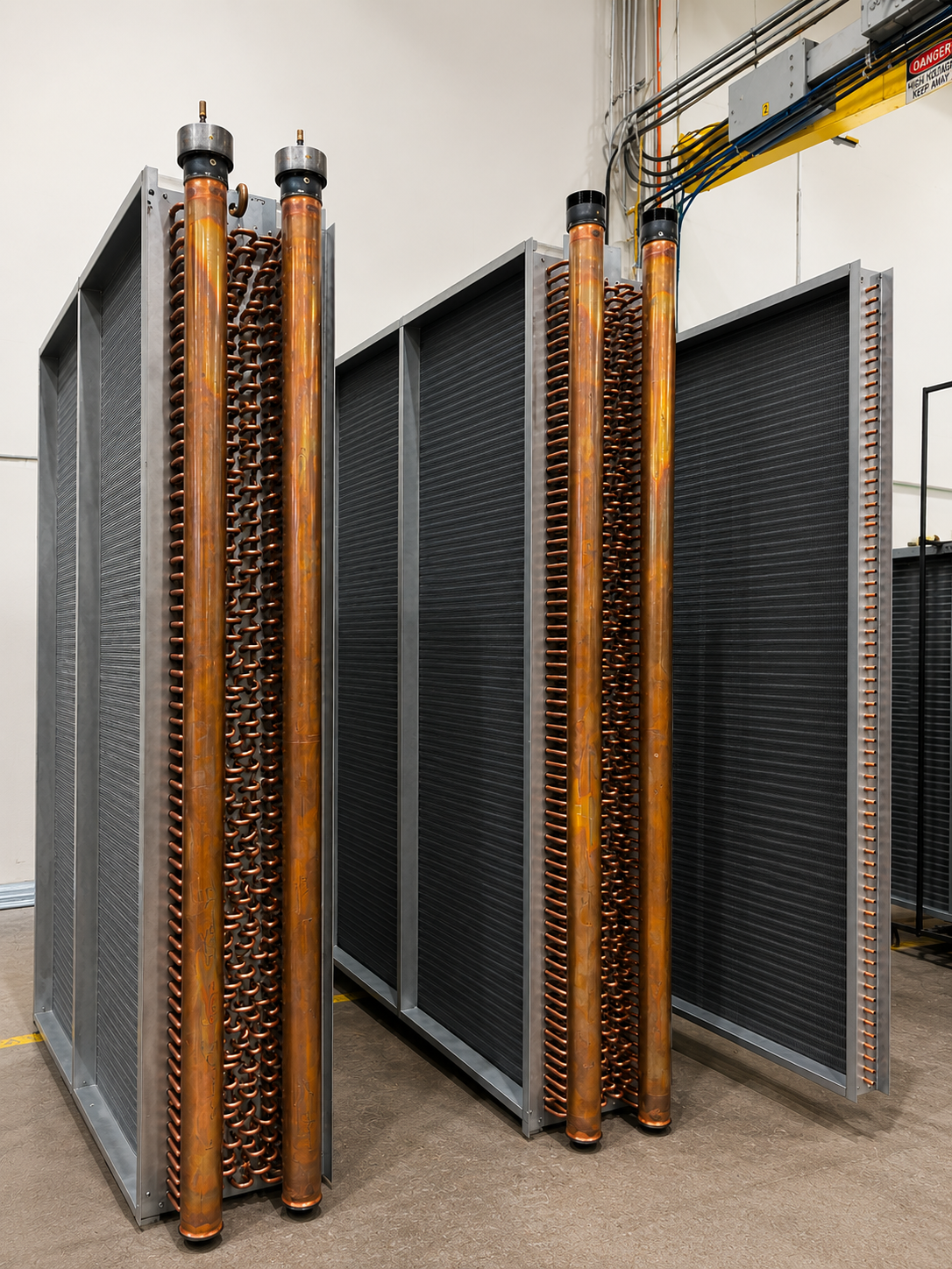
Why Lead Times Are Increasing
Historically, replacement HVAC coils could often be delivered within a few weeks. Today, lead times have expanded significantly due to a combination of factors:
- Record demand from data center construction
- Increased consumption of copper, aluminum, and steel
- Manufacturing labor shortages
- Limited production capacity
- Ongoing supply chain and freight challenges
As a result, many replacement coil orders now require substantially longer planning horizons than they did just a few years ago.
The Data Center Effect
Modern data centers operate around the clock and generate enormous amounts of heat. To maintain uptime, these facilities require extensive cooling infrastructure, including coils, air handlers, condensers, heat exchangers, and specialized cooling systems.
The rise of AI has accelerated this demand even further. New hyperscale data centers are being built at unprecedented rates, consuming manufacturing resources that were once readily available to the broader HVAC market.
When manufacturers commit production lines to large data center projects, fewer resources remain available for replacement coil production.
Why Quick-Ship Programs Are Struggling
Quick-ship programs have traditionally helped contractors respond to emergency coil failures. However, these programs depend on available manufacturing capacity and stocked materials.
Today, many manufacturers are facing:
- Fully booked production schedules
- Reduced raw material inventories
- Labor constraints
- Transportation bottlenecks
As a result, quick-ship options still exist but are often more limited and less predictable than in the past.
What Building Owners and Contractors Can Do
To minimize risk and avoid unexpected downtime:
- Plan replacements before failure occurs
- Monitor lead times regularly
- Work with experienced replacement coil specialists
- Discuss expedited options early in the project cycle
- Maintain strong supplier relationships
The Bottom Line
The rapid growth of data centers—and the AI boom fueling them—is fundamentally changing the HVAC industry. Longer replacement coil lead times and reduced quick-ship availability are becoming the new normal as manufacturers prioritize large-scale cooling infrastructure projects.
Organizations that plan ahead and partner with reliable suppliers will be best positioned to navigate these evolving market conditions and keep critical HVAC systems operating efficiently.
RELATED POSTS
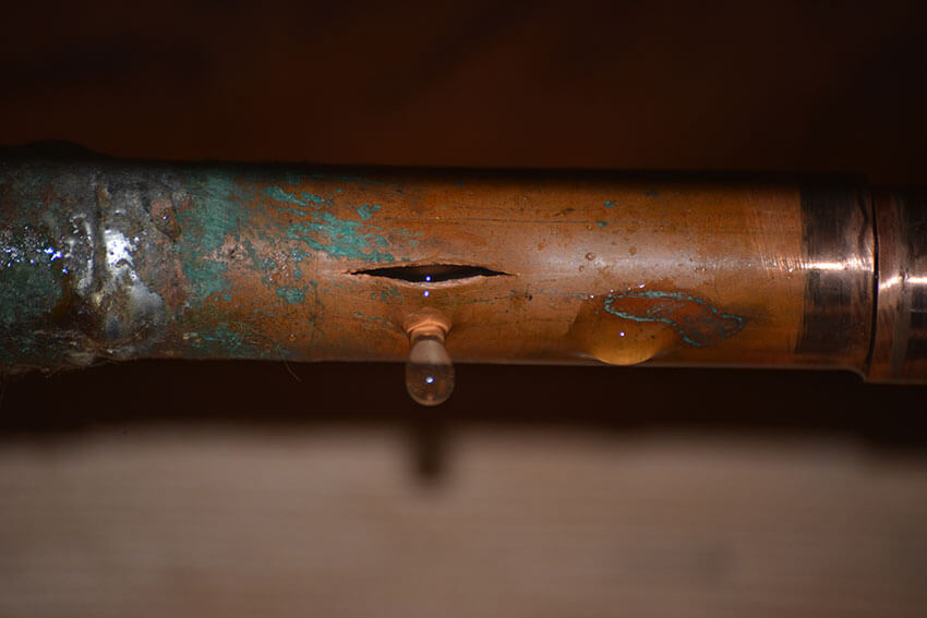
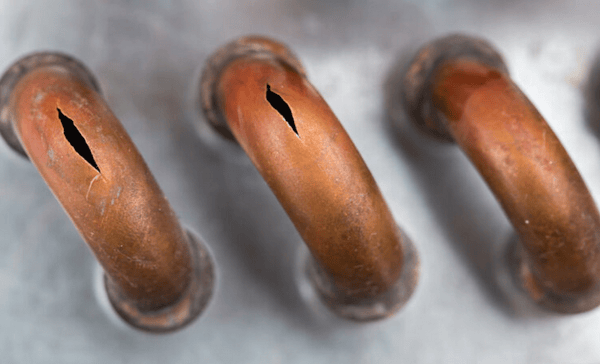
Why Cooling Coils Need to Be Replaced


 Were you aware that