In HVAC systems, understanding coils and counter-flow is critical for maintaining efficiency, preventing equipment failure, and ensuring long-term system reliability. Whether you work with chilled water coils, steam coils, DX coils, or hot water coils, correct installation and piping methods can dramatically impact performance.
Many HVAC issues begin with improper piping, poor condensate removal, and/or incorrect coil feeding. The good news? Most of these problems are completely avoidable when proper HVAC design principles are followed from the start.
This guide answers five of the most common questions about coils and counter-flow while explaining the real-world consequences of incorrect installation practices.
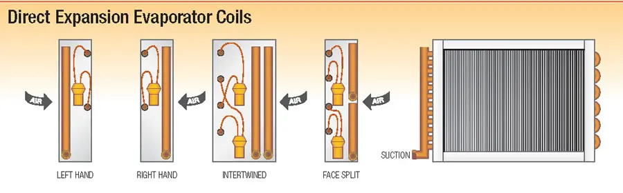
1. What Is Counter-Flow?
Counter-flow means air and water move in opposite directions through the coil.
- Air: Rows 1 → 8
- Water: Rows 8 → 1
This setup maximizes heat transfer and coil efficiency. Chilled water and DX coils are always designed for counter-flow operation.
Incorrect piping can reduce performance by 8–12%
2. Why Feed Water Coils from the Bottom?
Bottom feeding ensures all coil tubes receive even water flow.
Benefits:
- Better heat transfer
- Balanced performance
- Prevents “short circuiting”
Top feeding can cause uneven flow and reduced efficiency.
3. What Is Water Hammer in a Steam Coil?
Water hammer occurs when steam hits trapped condensate inside the coil.
Results:
- Loud banging noises
- Pressure shock
- Damaged coil joints and piping
Over time, this can lead to coil failure.
4. What Happens If Condensate Isn’t Removed?
Condensate can block steam flow and reduce heating performance.
Warning Signs:
- One side of coil feels warm
- Other side feels cool
Steam coils must:
- Be pitched properly
- Use steam traps and vacuum breakers
- Drain condensate continuously
5. Do Steam and Hot Water Coils Need Counter-Flow?
No. Steam and hot water coils do not require counter-flow piping.
Key Rule:
The steam supply should enter high, while condensate exits low.
Condensate must always leave the coil properly.
Best Practices
- Pipe chilled water coils in counter-flow
- Feed water coils from the bottom
- Properly drain condensate from steam coils
- Install steam traps correctly
- Follow manufacturer piping diagrams
If you have any questions or need assistance with installation, speak with one of our coil experts today!
RELATED POSTS
Tips on Hand Designation & Counter-flow


