Kennett Square, PA is widely known as the mushroom capital of the world. It is also located just a short drive from Capital Coil & Air’s sales office in West Chester, PA. Because of that proximity, we regularly receive requests from local mushroom farms to visit their facilities and measure failing DX coils for replacement.
Mushroom farms require precise climate control. Proper ventilation is critical because high CO₂ levels can negatively affect mushroom quality and growth. Humidity must also be carefully controlled. Mushrooms thrive in high-humidity environments, but too much moisture can lead to mold, bacteria, and serious crop losses.
That makes reliable HVAC equipment essential.
The Problem
One local mushroom farm had been dealing with multiple failing DX coils. Instead of replacing them, they had tried several temporary “band-aid” repairs. None of those repairs solved the issue.
As the coils continued to fail, the systems had to work harder to maintain the required growing conditions. That caused energy costs to rise while performance continued to decline.
A neighboring farm, which had already used Capital Coil & Air for several DX coil replacements, recommended that they call us to inspect the equipment.
What We Found
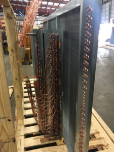
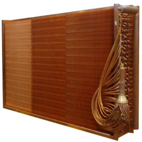
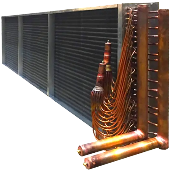
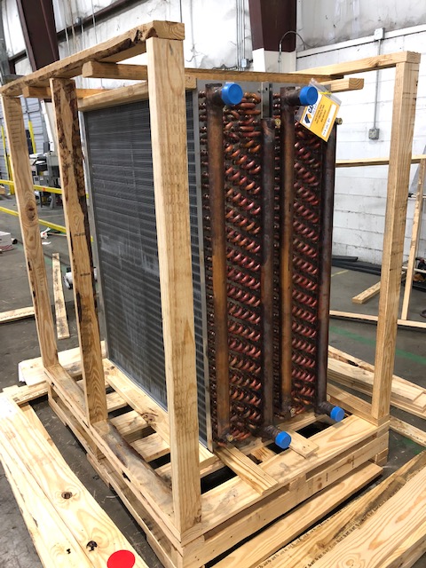
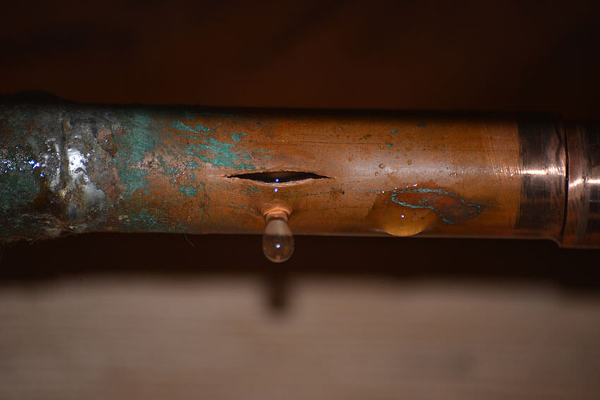
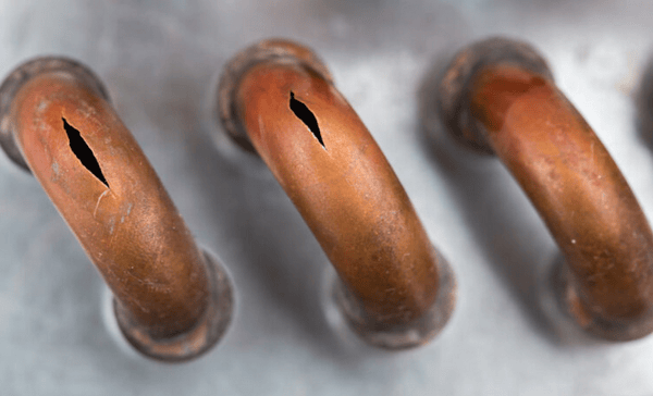
After inspecting several units, we found that the finned area on many of the coils had been severely damaged by corrosive elements in the air. The aluminum fins had deteriorated far faster than expected, which significantly reduced coil performance.
The original equipment had not included added coil protection, which made the coils vulnerable in such a harsh environment.
Because the new DX coils had to fit into the existing units, exact measurements were critical. We also recommended that any replacement coils include added protection, such as:
- Epoxy coating
- Stainless-steel casing
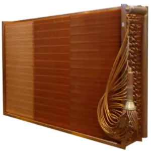
- Copper fins
- Other corrosion-resistant construction options
Without added protection, the farm would likely continue facing the same failures.
The Solution
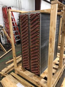
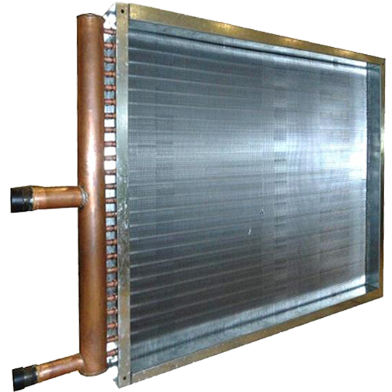
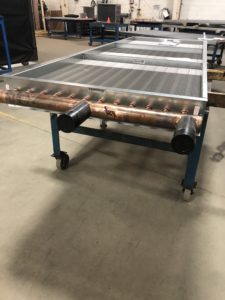
The farm decided to start with one replacement DX coil as a test. Capital Coil & Air measured the original coil, built an exact replacement, and supplied the new DX coil with an epoxy coating for added corrosion protection.
The coil arrived a few weeks later and matched the original unit perfectly.
One year later, the replacement coil was still operating at full capacity with no visible damage to the finned area.
The Result
Because Capital Coil & Air was able to respond quickly, identify the true cause of failure, and recommend a longer-lasting replacement solution, the farm moved forward with ordering the remaining batch of DX coils.
That successful project also led to additional referrals throughout the local mushroom farming community. Today, Capital Coil & Air is a trusted HVAC coil replacement supplier for many of the largest mushroom farms in the United States.
When corrosive environments destroy OEM coils too quickly, Capital Coil & Air can build exact-fit replacement coils with the right materials, coatings, and construction options to extend coil life and protect critical HVAC systems.
RELATED POSTS
Now Offering R-454B Refrigerant for All DX Coils


 Were you aware that