Top 5 Reasons Commercial HVAC Coils Prematurely Fail

Capital Coil & Air has come across virtually every scenario over the years in which a commercial HVAC coil had to be prematurely replaced, and we have since created an easy guide targeting the main reasons HVAC Coils prematurely fail.

  • Coil Plugging: If you are not changing filters and/or your commercial HVAC coils are not properly cleaned in a timely manner, your coil will actually begin to act as a filter. When dirt builds up on the coil, that blockage prevents heat transfer and can cause an approximate 20% to 40% drop in performance. Dirt adds to the coil resistance and can be a primary cause for your coil to fail prematurely.
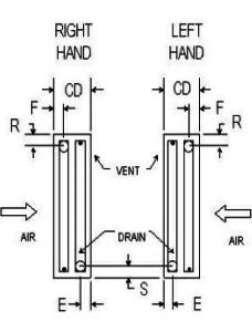
  • Vibration: When your HVAC coils are installed near a moving piece of equipment, vibration can occur and cause leaks. You can tell if vibration is the main cause if leaks are near the tube sheet and look like they are slicing through the tube. If/when that happens, the coils should be isolated from the rest of the system to prevent vibration from causing damage. One way to combat this is by oversizing the tubesheet holes, but many manufacturers will not do this. Condenser Coils are usually the most common victims of vibration.
  • Corrosive Environment: This applies to both the air in the environment and inside the tubes. For instance, if there is a corrosive element in the air, it will eat away at the copper tubes; whether you have 0.020” wall or 0.049” wall. This is very common in coastal areas where there may be salt in the air. To keep the costs down from going to a stainless steel or cupro-nickel coil, we usually suggest coating the HVAC coils. Coatings are almost always within your budget, and its application will only add about a week to the overall lead time. Steam condensate and untreated water can cause corrosion within the tubes of HVAC coils as well. If you have a steam coil that has failed before the one year warranty, there’s a great chance that corrosive agents are in the steam, and it’s eating away at the copper tubes.
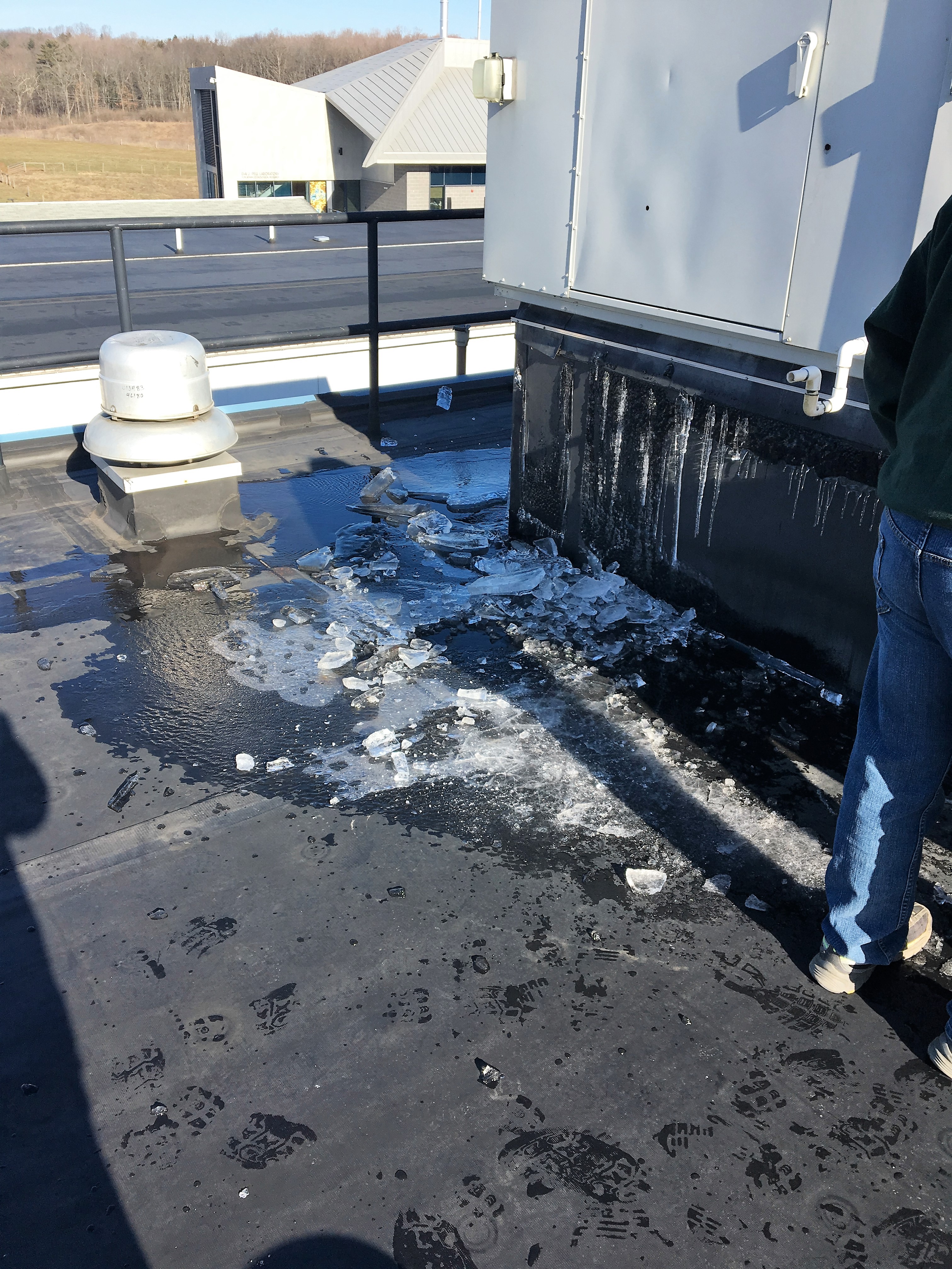
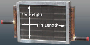
  • Freeze-Ups: Most people think that when HVAC coils freeze, the water or condensate laying in the coil freezes into ice and it expands causing the tubes to bulge and eventually spring leaks. What really happens is that the coil will freeze in multiple areas simultaneously, and it’s the pressure between these areas that cause the tubes to swell and eventually burst. These are very easy to spot as the leaks will run the length of the tube rather than around the tube.  ALSO be very careful when considering “freeze-proof” coils!  If you remove 5-6 inches from the fin length to make the “freeze-proof” application fit, your coil’s performance will suffer considerably. 
  • System Design: You would be amazed to learn how many HVAC coils were never designed properly for their systems. If there is a design problem, replacing the coil will only waste time and money; while you have done nothing other than duplicate the previous problem. A little known fact in the replacement market is that a high percentage of all our projects are because the coils were built incorrectly or were never designed correctly in the first place. In some cases, owners attempt to improve the coil’s performance by adding additional rows. Most however do this without taking into account the air pressure drop or fluid pressure drop that comes with it.

When dealing with an HVAC coil manufacturer, try to partner up with one who will walk you through the engineering and explain it along the way. Capital Coil & Air has well over a decade of experience and can help you diagnose whatever problem that you are experiencing correctly the first time. We look forward to working with you on your next project!

RELATED POSTS

Four Things That You Need When Buying Replacement Coils

Replacement HVAC Coils: 10 Common Ordering Mistakes

Coil Costs: What Will Make Your HVAC Coils More Expensive?


How to Make Sense of Heating Coils

Various winter storms have already ripped through multiple parts of the country necessitating the obvious need for working heating coils!!  With conditions such as these, emergencies with your HVAC systems are almost inevitable. THIS is precisely when you need your coil supplier to have the speed and flexibility to be able to tackle whatever emergencies arise.Steam Coil

Of all the types of HVAC coils available, heating coils are probably the easiest to select and understand. Capital Coil has listed the three most common types of heating coils that you are likely to come across.

Hot Water Coils

When looking at a water coil, the first thing to remember is that it is in effect “dumb”. In other words, water coils do not know the temperature of the water moving through it. While standard HVAC water coils are mostly constructed in the same design, the number of rows contained within the coil is a key differentiator in determining if the coil is hot water or chilled water. 99% of all hot water coils are (1) or (2) rows based on performance requirements. The “Delta T” between the entering air temperature and the hot water temperature is very large. As a result, you only need a coil with (1) or (2) rows to do the job. Face velocities across the coil can be anywhere from 600 to 1,200 FPM (feet/minute), while water velocities are usually 2-4 FPS (feet/second). As a result, you will always end up with a (1) or (2) row coil with somewhere between 8-14 fins/inch.

Booster Coils

Hot water booster coils are just another variation of the standard HVAC hot water coil.  They are always (1) or (2) rows as well, but the casing is designed for duct work installation. This basically means there is usually a 1” or 1.5” casing on all four sides of the coil. You select the proper size of the coil to make sure the air velocity across the coil is correct and simply transition the duct work to make the casing size around the coil.  Generally speaking, the size of the coil face is larger than the duct size, so you must transition the duct to make it larger. Just remember, a booster coil is nothing more than a standard hot water coil that is used for duct work installation.

There can also be a casing variation called “slip & drive”, where the coil is installed in the duct work. The coil does not have the standard casing on all four sides like a flanged coil. Capital Coil’s selection program allows you to pick either option.

Steam Coils

The real secret to any steam coil installation is to know that steam coils are much more of a product of the entire system than any other coil; meaning that other coil types are much more independent of the system.  Steam coils require numerous considerations, such as traps, pitched casing, piping flexibility, and vacuum breakers.  Steam coils are also built according to steam pressure through the tubes and headers.  2 – 50 psig is considered “low pressure” steam for coils, while 50-100 psig is considered “medium pressure”. Anything over 100 psig is considered “high pressure” steam.  An important fact to remember is that each of these categories requires a separate kind of construction with different brazing and different materials.  Additionally, almost all steam coils are (1) or (2) rows deep. Steam coils are known either as “standard” steam or “steam distributing”, but the differences are very easy to understand.  Outside air temperatures below 40˚F require that you have a “non-freeze” steam distributing coil.

RELATED POSTS 

Stock Hot Water Coils – Quick Buyers Guide

Your Goals as a Buyer of Commercial HVAC Replacement Coils

Coil Costs: What Will Make Your HVAC Coils More Expensive?


Chilled Water Coils – Circuiting Made Easy

Chilled Water Coil

Circuiting chilled water coils is one of life’s great challenges in the coil business. You’re bound to run across folks with years of experience in the industry that can not effectively explain this concept. While not the most exciting of subjects, the necessity of circuiting chilled water coils can not be overstated. Capital Coil & Air has attempted to simplify the idea of circuiting as much as possible.

For starters, circuiting chilled water coils is ultimately up to the performance of those coils. Circuiting is really a balancing act of tube velocity and pressure drop. In other words, think of a coil as a matrix. Each coil has a specific number of rows, and a specific number of tubes within each row. For example, a chilled water coil might be 36 inch fin height and 8 rows deep. The coil has 24 tubes in each row, and multiplied by 8 rows, there is a total of 192 tubes within the coil. While you can try to feed any number of tubes, there are only a few combinations that will work.

    • Feeding 1 tube – you will be making 192 passes through the coil, which will essentially require a pump the size of your car to make that process work.
    • Feeding 2 tubes – equates to 96 passes, and your pressure drop will still be enormous.
    • Feeding 3 tubes – 64 passes, which is still too many.
    • Feeding 4 tubes – See above.
    • Feeding 5 tubes – Impossible as 5 does not divide evenly into 192 (passes).
    • Feeding 6 tubes – Still constitutes far too many passes, which again leads to additional pressure drop.
    • Feeding 7 tubes – Same rule for feeding 5 tubes.
    • Feeding 8 tubes –  Same rule for feeding 6 tubes.
    • Feeding 24 tubes – This feed consists of 8 passes, which is in the ballpark, and with a pressure drop you can live with.
    • Feeding 32 tubes – 32 tubes will see 6 passes. You might see a slight decrease in performance, but it’s off-set by a continuously better pressure drop.
    • Feeding 48 tubes – The magic combination, as 4 passes typically elicits the best performance and pressure drop simultaneously.


Rule #1: The number of tubes that you feed must divide evenly into the number of tubes in the chilled water coil.

Rule #2: The chilled water coil must give you an even number of passes so that the connections end up on the same end.

Rule #3: Based on the number of passes, you must be able to live with the resulting pressure drop. Acceptable tube velocity with water is between 2 and 6 ft. per second.

You’re bound to run into different terminologies depending on the manufacturer. More times than not, the different verbiage confuses more than it clarifies. However, understanding the basic tenets of chilled water coil circuiting will remove much of the perceived difficulty.  

Related Posts

Coils and Counter-flow: 5 Common Questions

Chilled Water Coils & Moisture Carryover

Top 10 Things You Need to Know About Chilled Water Coils


Condenser Coil Failing? Here’s probably why….

Did you recently turn on your DX systems only to find your Condenser Coil is not working?  Simple fix right?  Unfortunately, no.  If you get lucky, you can send us the model number of the unit, and there’s a great chance we’ve already built it.  In the case that we do not have that model number on file, you have two options.  You can go back to the original manufacturer, wait (5) months for a part and pay through the roof.  Or you call Capital Coil, and we’ll walk you through the engineering it takes to replace a condenser coil.                                                                      Condenser Coils

Very rarely do condenser coils ever freeze so the first thing you’re going to want to know is if your coil died of corrosion, old age, or possibly vibration.  Old age is obviously preferable because with a few easy dimensions, we’ll have enough to price up your duplicate coil.  Condenser coils are usually outside and are easily accessible for measurements and digital pictures.  With just the size, the rows, and fins/inch, you can get a price.  And digital pictures of the headers and return bends will give us a good idea of the circuiting and sub-cooler circuits. 

If the coil has been eaten away by corrosion, it was an improper design to begin with.  Most people don’t know that salt in the air will ruin aluminum fins within a year or two.  There are two ways to combat this.  The first option is to make the switch to copper fins and stainless steel casings.  While this will extend the life of your coil considerably, most people are not too happy about the additional cost over aluminum fins.  The second option is to use a coating.  Coatings are the much more popular choice.  They are a fraction of the cost as copper fins and only add (1 – 2) weeks to your lead time. 

When your HVAC coils are installed near a moving piece of equipment, vibration can occur and cause leaks.  The area where these leaks occur is very important and will clue you in to if the problem is vibration.  If they are near the tube sheet and look like they are slicing through the tube, the coils should be isolated from the rest of the system to prevent vibration from causing damage.  One way to combat this is by oversizing the tube sheet holes, but many manufacturers will not do this.  Condenser coils are usually the most common victims of vibration.

The last concern is with cleaning condenser coils.  Since condenser coils see outside air almost exclusively, they need to be cleaned more than other coils.  The reason for this is most condenser coils have fin spacing of 12-20 fins/inch.  With fins that tight together, the coil can and will act like a filter.  And when the coil is clogged up, the performance suffers greatly.  Recently, we’ve been getting more and more calls about using a heavier fin thickness.  This is to help with high pressure cleaning and corrosive cleaning agents. 

When dealing with an HVAC coil manufacturer, partner up with one who will walk you through the engineering and explain it along the way. Capital Coil & Air has well over a decade of experience and has seen every issue to make sure your everything from the quote to the installation go smoothly! Give us a try on your next project!

RELATED POSTS

Top 5 Reasons HVAC Coils Prematurely Fail

You should never have to worry about performance on replacement coils. Well… almost never!

Repair or Replacement HVAC Coils?


Need A Replacement For A Bell & Gossett Heat Exchanger

Bell & Gossett tube bundle or heat exchanger fail on you? Capital Coil offers direct replacements for most B&G Models, and we have quick build options to get you up and running fast.  Just send us the model number and a picture of the nameplate if you can and we’ll get you a quote asap.Tube Bundle

Useful Information when determining your model:

  • Steam to Liquid or Liquid to Liquid
  • 2- Pass, 4-Pass or 6-Pass
  • Single tube or double tube
  • High Pressure or low pressure


RELATED POSTS

Top 10 Hints for Replacing Tube Bundles in U-Tube Exchangers

Replacing a Shell and Tube Heat Exchanger? And Have the Model Number?

Need A Replacement Heat Exchanger/Tube Bundle?


Looking For A Trane Replacement Coil

If you need Trane replacement coil within a Trane system, but aren’t sure about the dimensions or decoding the model #, send this to Capital Coil & Air for pricing. On most Trane AHU’s, the AHU model #, as well as the coil or “part #”, is listed as “Service Model No Coil”. If you see this, send it over, and the sales team at Capital Coil will handle the rest. Great pricing with the ability to be built as fast as is needed!Trane replacement coil


Frozen Steam Coils: How Do You Prevent This?

Regardless if you have steam coils or steam distributing (non-freeze) coil, you can freeze ANY coil.  When freezes happen, everyone immediately looks to the steam coil as the cause.  When in fact, there are numerous reasons that must be looked at well before the coil.

Freezes generally happen in older systems, however if your new system is not maintained properly or correctly installed, your steam coil can and will freeze.  For instance, you’d be surprised at how many times dampers are left open, controls fail, freezestats don’t work, etc.Steam Coils

In a Standard Steam or Steam Distributing Coil, a freeze-up can occur when condensate freezes within the tubes of the steam coil.  The two most common reasons for freezing steam coils are the steam trap and the vacuum breaker.  The function of steam trap is to remove the condensate as soon as it forms.  Condensate usually collects in the lowest part of the coil.  If your steam trap isn’t installed properly, that condensate will lay in the coil and it will inevitably freeze as soon as it sees outside air.  The vacuum breaker also helps clear the condensate, minimizes water hammers, and helps with uneven temperatures. This must be installed on the control valve and always above the steam trap.

Unfortunately, there are no ways to determine exactly where your steam coil will freeze.  And a common misnomer is that the condensate turns to ice and the expansion is what causes the tubes of the coil to pop.  In reality, it’s the pressure that builds up between freeze points.

Here’s couple tips in your coil design that can help prevent your standard steam and steam distributing coils from freezing:

  • Standard steam coils should NEVER see any outside air below 40 degrees.  If it does, steam distributing is the only way to go!
  • 5/8” OD Steam distributing coils over 72” long are recommended to have a dual supply
  • 1” OD Steam distributing coils over 120” long are recommended to have a dual supply
  • Make sure your steam coil is pitched if possible.  This slopes the condensate to the return connection making it easier to remove the condensate

Give Capital Coil & Air a try on your next project. Our engineering, pricing and service is the best in the industry!

RELATED POSTS

Heating Season Will Soon Be Upon Us

Commercial Steam Coils; Lengths & Controls

Types of Steam Coils


Top 10 Fan Coil FAQ’s

1. A fan coil is among the easiest units to understand in the HVAC industry.  Basically, there is a small forward curved fan, a coil, and sometimes a filter.  They are all direct drive units. Click HERE to see Capital Coil’s full Fan Coil Product Lineup.

2.  Fan coils run from 200 CFM to 2200 CFM, which is 0.5 ton through 5.5 tons.  Anything larger than these sizes requires a belt drive unit…which is really a full fledged air handler.

3.  The thing that differentiates fan coil units is where and how they are going to be installed.  Is the unit going to be hidden above the ceiling or maybe in a closet?  Or is it going to be exposed so that everyone can see it?  Will it be ducted or will it just pull air from the space where it’s located?  These are things that determine the configuration of the unit and which style of unit to choose.  But, every unit has 3 things in common:  fan, coil, and sometimes a filter.

Fan Coil 4.  Some units have (2) coils.  One for heating and one for cooling.  Obviously, there is a separate supply and return connection for each coil and these units are known as 4 pipe fan coils.  Many units only use the same coil for both heating and cooling and these units are 2 pipe fan coils.

5.  Units are either horizontal or vertical depending on the orientation and flow of the air.  A typical fan coil in a hotel room is a vertical unit with a mixture of air coming from outside and the air recirculating in the room.  The air enters at the bottom of the unit and is drawn upward through the fan.  This makes the unit a vertical style.  Many units are horizontal with the air entering at the back of the unit and traveling horizontally through the unit.

6.  Almost all fan coils are 3 speed or infinite speed settings based on the controls.  The high speed gives you more BTU’s, but more noise too.  Because the unit is direct drive, when you dial down the speed, you also dial down the performance.

7.  Coils in the units tend to be 3 or 4 row deep coils.  3 row is typically used the most, but if you need the extra performance, 4 row is the way to go.  Performance is always governed by the cooling aspect.

8.  Fan coils sometimes have short runs of duct work and there is static pressure on the unit.  Static pressure reduces the amount of CFM and BTU’s that the fan coil can give you.  This is true of both horizontal and vertical units.  Most performances listed on charts that you will see are static free performances.

9.  The control systems for fan coils are often more complicated and more expensive than the units themselves.  There are balancing valves, isolation valves, unions, y-strainers, p/t plugs, air vents, ball valves, thermostats, condensate float switches, and disconnects.  Capital Coil & Air can do this at the plant, but it is much cheaper and easier to do it at the installation. 

10.  Just describe your installation requirements to a sales engineer at Capital Coil & Air and they will guide you to the right design and configuration of the unit for you.  It requires only a phone call or e-mail! We look forward to working with you!


RELATED POSTS

Top 10 Chilled Water Coil Facts

Light-Duty Commercial Belt Drive Air Handlers

Top 10 Questions You SHOULD Be Asking Your Coil Supplier


What Is Meant By A “Bank” Of Chilled Water Coils

For those that work with HVAC installations on a regular basis, you have run across the problem of needing to install new chilled water coils in very tight, confined areas. The coil is too big to fit in the Chilled Water Coilselevator, and/or the HVAC room is so small that you are likely to damage the coil simply by moving it. As a solution to this challenge, chilled water coils are often installed in “banks” of coils. You are most likely to see this configuration in Air Handler Units, as well as “built-up” systems. Due to face velocity limitations across the coil, you will need larger coils in order to meet your required face area. With this in mind, there are a few specific reasons why you want to avoid having a single, large coil in one of your units.  Starting with the obvious: larger coils are much more difficult to transfer and install. This is especially true for older buildings, where the rooms were essentially built around the HVAC system.

As you’ve probably experienced, some of these areas can barely fit a single person, so installation – if even possible – is a logistical nightmare. Also, the larger the coil, the easier it is to damage during transport to the jobsite. To avoid these issues, simply break down the single, larger coil into smaller coils. When piped together, those smaller coils are stacked into “banks” of coils in the system. If installed correctly, this “bank” should have the same performance as the larger, single coil.

Casing

There are many different casing options available, but “stackable” flanges are required for heavy chilled water coils that are “banked”. The flanges are often inverted inward and down to give added strength to the casing, which is needed due to the fact that another coil of equal weight will be stacked on top of it. When ordering coils in a “bank” configuration, be sure to let the manufacturer know that they will be “stacked”.

Many engineers also use stainless steel casings on chilled water coils. While more expensive than traditional galvanized steel, stainless steel protects against excessively wet coils and/or corrosive elements in the airstream. Keep in mind that the majority of coils fail because of old age and its casing, as opposed to failure with the coil’s core. With that in mind, doesn’t it make sense to select heavy-duty stainless steel casings that are more durable and meant for stackable installations?

Drain Pans & Water Carryover

Water Coils

All chilled water coils must be sized so that the face velocity across the coil does not exceed 550 ft/minute. Water on the outside of the coil is carried away from the coil’s leaving air side in an arc, while water in the highest point of the coil is carried further down the unit or ductwork. “Stackable” coils often require intermediate drain pans under each coil to catch the excess water carryover. Each coil in a bank requires its own drain pan, as a single, large pan under the bottom coil is not enough.

Circuiting/GPM

If all of the coils in a “bank” are of equal size and handling the same CFM, then the GPM of each coil will also be the same.

Always feed the bottom connection on the supply header on the leaving air side of the coil. This ensures counter air and water flow. This also prevents the coil from short circuiting because the header fills first and circuits all of the tubes equally.

Designing Banks Of Coils

Almost all coil “banks” perform more efficiently if you design something more square in shape, as opposed to long and/or high. In a “bank” of coils, you may find that one coil has points of 300 ft/minute, with other points at 800 ft/minute. Scenarios such as this will cause water-carryover! You generally want to be as close to 550 ft/minute as possible in order to allow equal airflow distribution across the face area of the coil.

Anytime you are designing and/or building coils, work closely with the manufacturer as an added resource to ensure that you are getting the ideal solution for your HVAC system. Capital Coil & Air works on similar jobs such as these daily, and we welcome the opportunity to work with you in whatever capacity is needed.

RELATED POSTS

Top 5 Reasons HVAC Coils Prematurely Fail

Coils and Counter-flow: 5 Common Questions

Chilled Water Coil Circuiting Made Easy


Top 10 Tips For Measuring HVAC Coils

1. When measuring HVAC coils, performance has very little to do with accurately measuring for replacement coils. Fitting the coil in the existing space with the least amount of labor has everything to do with measuring a coil.  If you duplicate the coil in almost every respect, the performance will match and take care of itself.  New is always more efficient than old.

2.  If you’re ever in doubt about a dimension, smaller is always better than bigger. You can always “safe off” around any coil as long as you can fit it in the space.  If a coil is too big, it makes a really ugly coffee table in your shop.  Too big is the enemy of measuring coils.

Chilled Water Coil

3.  The fin height and fin length are not the determining factors in measuring a coil. The overall casing dimensions are the most important, and you work backwards to determine fin dimensions.

4.  The depth of any coil is the total casing depth in the direction of airflow. The height is the number of tubes high in any row.  Depth is a function of rows deep and height is a function of tubes in a row.

5.  Overall length (OAL) is not the fin length and it’s not the casing length. It is the length from the return bends to include the headers that are inside the unit.  Again, it is necessary to work backwards to get the other dimensions once you know this critical dimension.

6.  Circuiting is the number of tubes connected to the supply header. Generally, you just want to count the number of tubes connected to the header and that will tell you whether it’s full, half, or even a double circuit.  It does not matter how the return bends are configured.  Your goal is to count the number of supply tubes and all performance is based on that.

7.  Fins are measured in fins per inch. Hold a tape measure up to the coils and count the number of fins in one inch.  If you can’t get in to take the measurement, a safe rule of thumb is 10-12 fins/inch.  That will work on almost every coil.  The exception to that rule is a condenser coil.  14-16 fins/inch on a condenser coil is usually pretty safe.

8.  Connection locations are difficult only if you are using the existing piping in the system (which are welded). Copper piping is brazed and can be changed easily.  If a system is old and the piping is being replaced as well as the coil, the connection location is not a major deal.  It’s very easy to match up!

9.  With replacement coils, the concept of “left hand vs. right hand” doesn’t actually exist. Connections are “top left-bottom right” or vice versa.  Ideally, all coils should be counter-flow which means that the water and air flow in opposite directions.  The air hits row one first and the water is piped into row eight first.  However, there are lots of installations that are piped backwards, and they work just fine.  Just match them up, and the coil’s performance will be equal to the old coil.

10.  Connections are not measured from the top of the header! They are measured from the top of the casing to the centerline of the connection.  Or the bottom of the casing to the centerline.  You need a point of reference, and the header height can be anything just as long as it doesn’t stick above or below the casing height.


All of the above “suggestions” or “secrets” are in no particular order.  They are just things that you should know to ensure that you are selecting the correct replacement coil. While most seem like common sense, your best bet is to talk with the sales team at Capital Coil & Air, who can walk your through the entire process and help you to fill out coil drawings when trying to measure the dimensions.

RELATED POSTS

Replacement HVAC Coils: 10 Common Ordering Mistakes

The Smart Approach to Buying HVAC Coils (and Saving Money)

Top 10 Chilled Water Coil Facts