1. Hot or chilled water coils are still water coils. There is really no difference between hot water coils and a chilled water coils in construction. Hot water coils are usually 1 or 2 rows and chilled water coils are usually 3 to 12 rows deep.
2. The vast majority of chilled water coils are constructed from either 1/2″ OD tubes or 5/8″ OD tubes. A lot of that depends on the tooling of the original equipment manufacturer and what is more economical. Either size can be used and substituted for each other, which makes replacing your coil that much easier.
3. 1/2″ Tubes are on 1.25″ center to center distance. 5/8″ tubes are on 1.5″ center to center distance. For example, if a chilled water coil has a 30″ fin height, there will be (24) 1/2″ tubes per row or (20) 5/8″ tubes per row. The tube area of the coil is remarkably the same. They are almost interchangeable.
4. The quality of the coil often times is directly tied to the tube thickness. Many installations have water not treated properly or tube velocities that are too high. There are few perfect installations in real life. Increasing the tube wall thickness on a chilled water coil is a great way to ensure longer life.
5. Fins make great filters! Of course, they are not designed to be filters, but it happens. You can make any coil cheaper by making them 14 fins/inch with less rows rather than 8 or 10 fins/inch. Just remember that deep coils are very difficult to clean. Cheap is not the way to go most of the time!
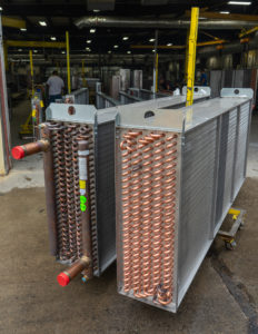
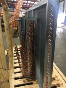
6. Fins are designed for maximum heat transfer. They are much more complicated in design than they appear to be when looking at the chilled water coil. They are rippled on the edge to break up the air. They are corrugated throughout the depth of the fin. The tubes are staggered from row to row and the fin collars are extended. All of this to maximize heat transfer. Unfortunately, the byproduct of this is the fins can end up being great filters. Be careful in the design of any chilled water coil.
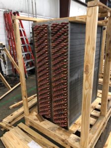
7. Fins are aluminum for a reason! They give you great heat transfer at an economical cost. You need a compelling reason to switch to copper fins as copper is very expensive, and you’re likely to double (or maybe triple) the cost of the coil. Coatings are popular for this very reason.
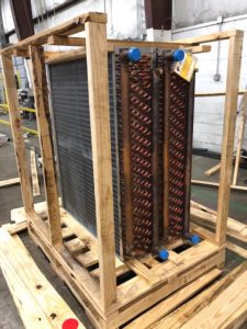
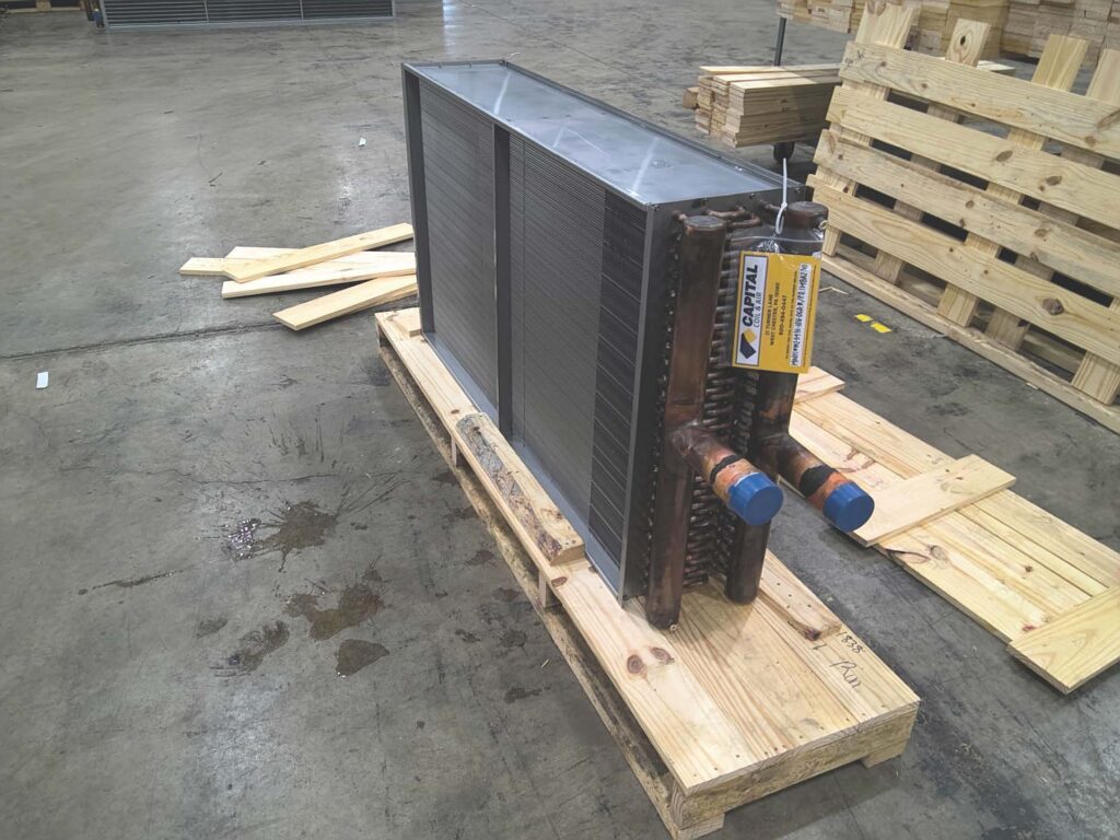
8. Many chilled water coils are built with 304 stainless steel casings. The casings are stronger, they last longer, they are stackable, and it’s fairly inexpensive. After all, what is the point of building the best coil possible and have the casing disintegrate over time around the coil? Sometimes, it’s money well spent!
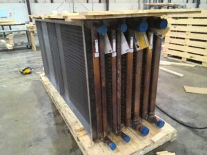
9. Circuiting the coil is the tricky part of any coil. Circuiting is nothing more than the number of tubes that you want to feed from a header. There are two rules. You must keep the water velocity over 1 foot/second and below 6 feet/second. 3-4 feet/second is optimum. The second is the number of tubes that you feed must divide evenly into the number of tubes in the coil.
10. Replacing your chilled water coil is easy. Rarely do you have to worry about the performance. When you replace a 20 year old coil, it is dirty and the fin/tube bond is not good. The coil is probably operating at 1/2 of its capacity at best. When you put a new coil on the job, your performance will automatically be terrific. Your main concern is now making the sure the coil physically fits in the space allowed. And always have this in the back of your mind: Smaller is always better than too large. Smaller you can always work with, whereas too large makes for a very ugly and expensive coffee table.
There you have it – everything you need to know about chilled water coils. Interested in learning more, please reach out to Capital Coil & Air! We look forward to the opportunity to be your coil replacement specialists!
RELATED POSTS
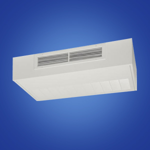
DX & Chilled Water Cabinet Coils